
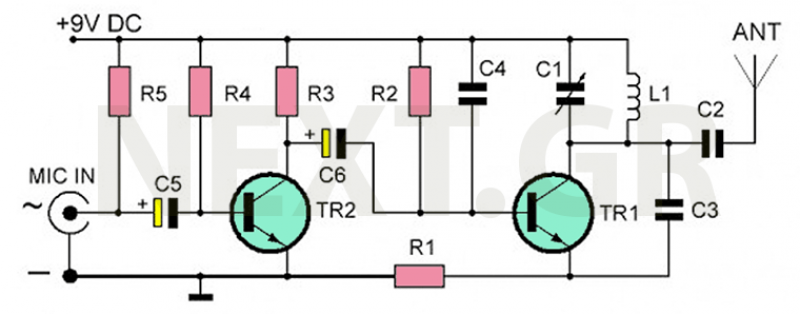
FM Wireless HI-FI circuit

The module can operate independently even for some high frequencies, as it lacks power and a pre-emphasis network consisting of resistors R7, R8 and capacitor C6, which are designed to enhance the quality of transmission at higher frequencies. The circuit requires an input level of 100 mV RMS to achieve a sufficient modulation rate, necessitating a preamplifier for the microphone. This function is performed by IC1, configured as a standard inverting amplifier with adjustable gain via potentiometer P1. The supplied microphone is an electret model, with its power circuit formed by resistors R1, R2, and capacitor C1. A conventional dynamic microphone or an external electret microphone with an integrated power supply can also be used, in which case R1, R2, and C1 would be omitted.
The transmitter utilizes an Aurel module, which is an FM audio receiver. This module is also a compact circuit board that contains all necessary components for the receiver, equipped with a squelch circuit. The audio output occurs at pin 10 of the module and must be decoupled through capacitor C4 to mitigate the effects of the pre-emphasis circuit used in transmission. The audio frequency (AF) level output from the module may be insufficient for certain high-fidelity amplifiers or mixers, typically only reaching 100 mV in optimal conditions. This output is amplified slightly through IC1, which serves as a classic preamplifier. The preamplifier is powered continuously by the Aurel module, receiving its power from pin 18 of the module. This output is controlled by the internal noise circuit, which activates the power when valid audio is detected. The operating threshold of the squelch circuit is adjustable via potentiometer P2, the only external control for the receiver. The power supply must be regulated to 5 volts, which is achieved by IC2, capable of accepting input voltages from 9 to 15 volts, typically sourced from an associated amplifier or a wall power supply. The low power consumption of the entire setup, approximately 30 mA, facilitates this power supply design.
The circuit's design emphasizes efficiency and compactness, making it suitable for applications requiring reliable FM audio transmission. The integration of adjustable components allows for flexibility in use, accommodating different microphone types and ensuring optimal performance across various operating conditions. The careful selection of components and circuit configuration supports high-quality audio transmission, while the power management features ensure stable operation under varying load conditions.Circuit To relieve you of any concern related to high frequency, I used a module ready, in case a module Aurel audio FM transmitter. This tiny circuit board with 2 cm by 4 cm supports a transmitter modulation frequency track, delivering an RF power of 10 mW which is quite sufficient for the desired use.
As it is driven by a resonator surface wa As you can see the review of the scheme, the module can stand alone even for some HF itself since it lacks power and a network of pre-emphasis R7, R8, C6, designed to improve quality transmission of higher frequencies. The input level required by the circuit to achieve a sufficient modulation rate of 100 mV rms, a preamplifier is necessary for our microphone.
It is the role of IC1, mounted on a very classic inverting amplifier with adjustable gain through P1. The provided microphone is a model electret with its supply circuit formed by R1, R2 and C1, but you might as well use a conventional dynamic mic, or an external electret microphone with its integrated power supply in which case R1, R2 and C1 disappear.
As to the transmitter, I used a module Aurel, which is an FM audio receiver. It also appears as a tiny circuit board containing all the components of the receiver, equipped with a squelch circuit or quiet as I put to good use. As illustrated, the audio output takes place on the leg 10 of the module and should be dG©saccentuG©e through capacitor C4 to offset the effect of pre-emphasis circuit used in the show.
The AF level issued by the module may be insufficient for some high fidelity amplifiers or mixers certain: it is only 100 mV in the best cases I amplifies a bit through rose IC1 very classic. This preamplifier is fed continuously as the module Aurel but instead receives its power through the leg 18 of the latter.
This output is in fact controlled by the internal circuit noise and is connected to power when the circuit noise estimates have detected a valid issue. The operating threshold of the muffler is adjustable and is obviously the role of the potentiometer P2 is the only external control of the receiver.
The food in turn must be regulated to 5 volts, which is made by IC2 which can receive input from 9 to 15 volts from such amplifier associated with a block or sector-style outlet. The low power consumption of the arrangement (of the order of 30 mA) makes this power supply. 🔗 External reference
Related Circuits
The diagram illustrates a series connection of cell diode capacitors, each rated for an increasing voltage of 300 V. This configuration generates a high DC voltage supply of 40 kV, which can be utilized for various experimental applications. With...
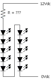
The color of the LED makes a significant difference. The type and size of the LED, such as 3mm or 5mm, and the power source are crucial factors to consider. More information is required for accurate calculations. A basic...
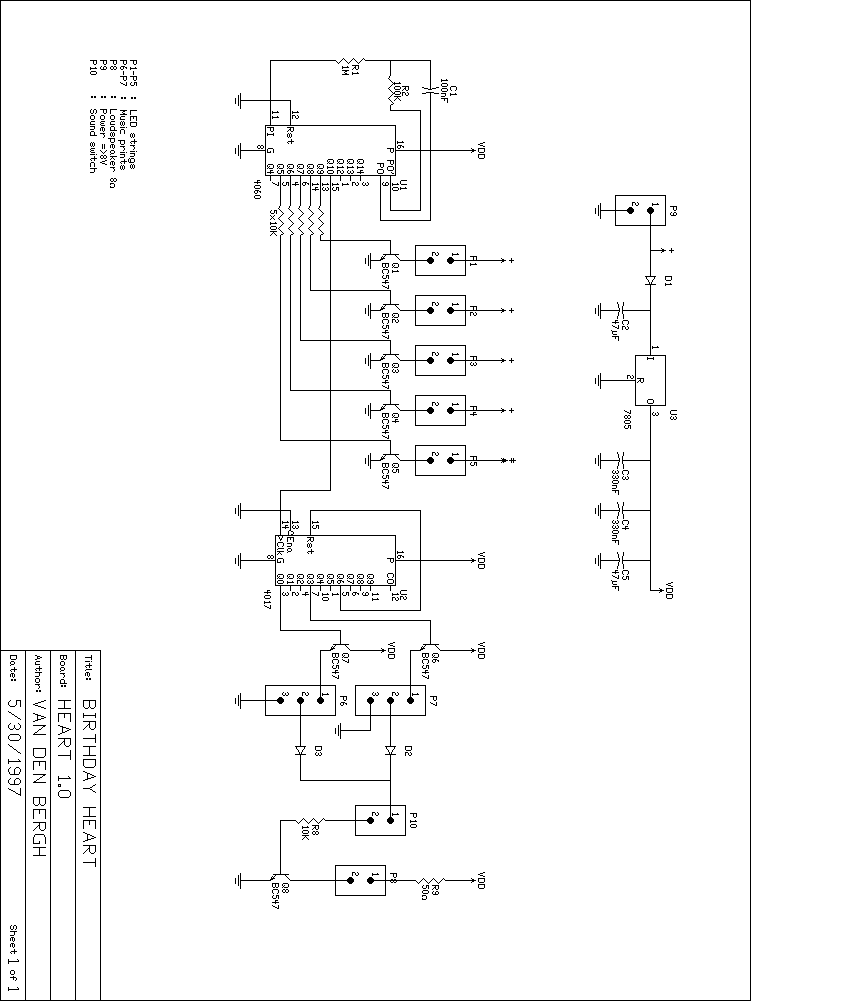
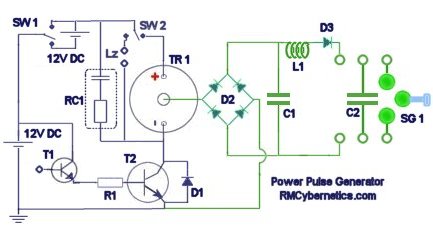
This is a birthday heart circuit. No much description is available but you can use your experienced imagination! The birthday heart circuit is designed to create a visually appealing display, often used as a decorative element for celebrations. The circuit...
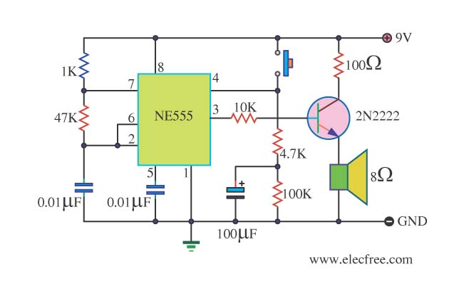
This is a danger beep circuit. It uses a 555 integrated circuit configured as a stable multivibrator that provides a duty cycle of 5% to drive a loudspeaker. The danger beep circuit utilizes the 555 timer IC, a versatile and...
The recommended transmitter is straightforward to construct and suitable for beginners. Despite its simple design and compact size, it delivers remarkable performance. It operates for 12-15 hours on a 9-volt battery and has a transmission range of 100 to...
This is a VU meter analog circuit. The circuit is connected to the line terminals of the amplifier. The VU meter operates simply, with T1 and T2 indicating signal increases. The VU meter circuit is designed to visually represent audio...