
high voltage circuits

The circuit design consists of multiple stages of capacitors and diodes arranged to form a voltage multiplier. The initial stage begins with a standard 12 V power supply, which is fed into the first capacitor and diode pair. Each capacitor is charged to the input voltage, while the diode prevents reverse current flow, allowing the capacitor to hold its charge. As the voltage progresses through each subsequent stage, the capacitors charge to higher voltages, effectively multiplying the input voltage.
In this configuration, each capacitor is rated for 300 V, ensuring that the components can handle the increasing voltage levels without failure. The use of four doubler stages enables the final output to reach 160 kV, suitable for high-energy experiments. The circuit's design must be carefully considered to ensure that all components are rated for the maximum expected voltage and that proper insulation and spacing are maintained to prevent arcing.
The high voltage DC power supply produced by this circuit is particularly useful for applications in scientific research, where it can be utilized to power devices such as electron tubes and x-ray tubes, which require stable and high voltage inputs. Furthermore, the capability to drive Tesla coils and other high-power coils makes this power supply versatile for various experimental setups, including demonstrations of electrical phenomena and high-voltage experiments.
Safety precautions are paramount when working with high voltage systems. It is essential to incorporate proper enclosures, use insulated tools, and ensure that all components are securely mounted to prevent accidental contact. Additionally, adequate grounding and discharge mechanisms should be implemented to mitigate the risks associated with high voltage operation.The diagram shows a set of cell diode capacitor connected in series, each set of increasing voltage 300 V. This Supply generates DC high voltage 40kV, with which you can make interesting experiments. With the available 40 kV capacitors, 160 kV output voltage could only be obtained with four doubler stages.
Estimated voltage output is 9kV from 12V supply. High voltage DC power supplies are used by science enthusiasts for powering electron tubes and x-ray tubes. A Multipurpose power pulse generator capable of driving Tesla Coils and other high power coils. 🔗 External reference
Related Circuits
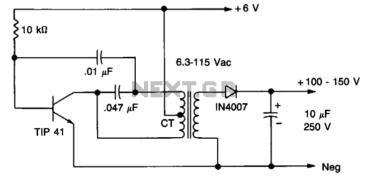
A 6 V battery can provide 100-150 Vdc center-tapped at a high internal impedance (not dangerous though it can inflict an unpleasant jolt). A 6.3 V transformer is connected in reverse with a transistor used in a Hartley oscillator...
This constant current constant voltage switched-mode power supply (SMPS) is designed for efficient battery charging. The circuit outputs a constant voltage of 7.2V and a constant current of 600mA. The operation mechanism is straightforward: when the load impedance is...
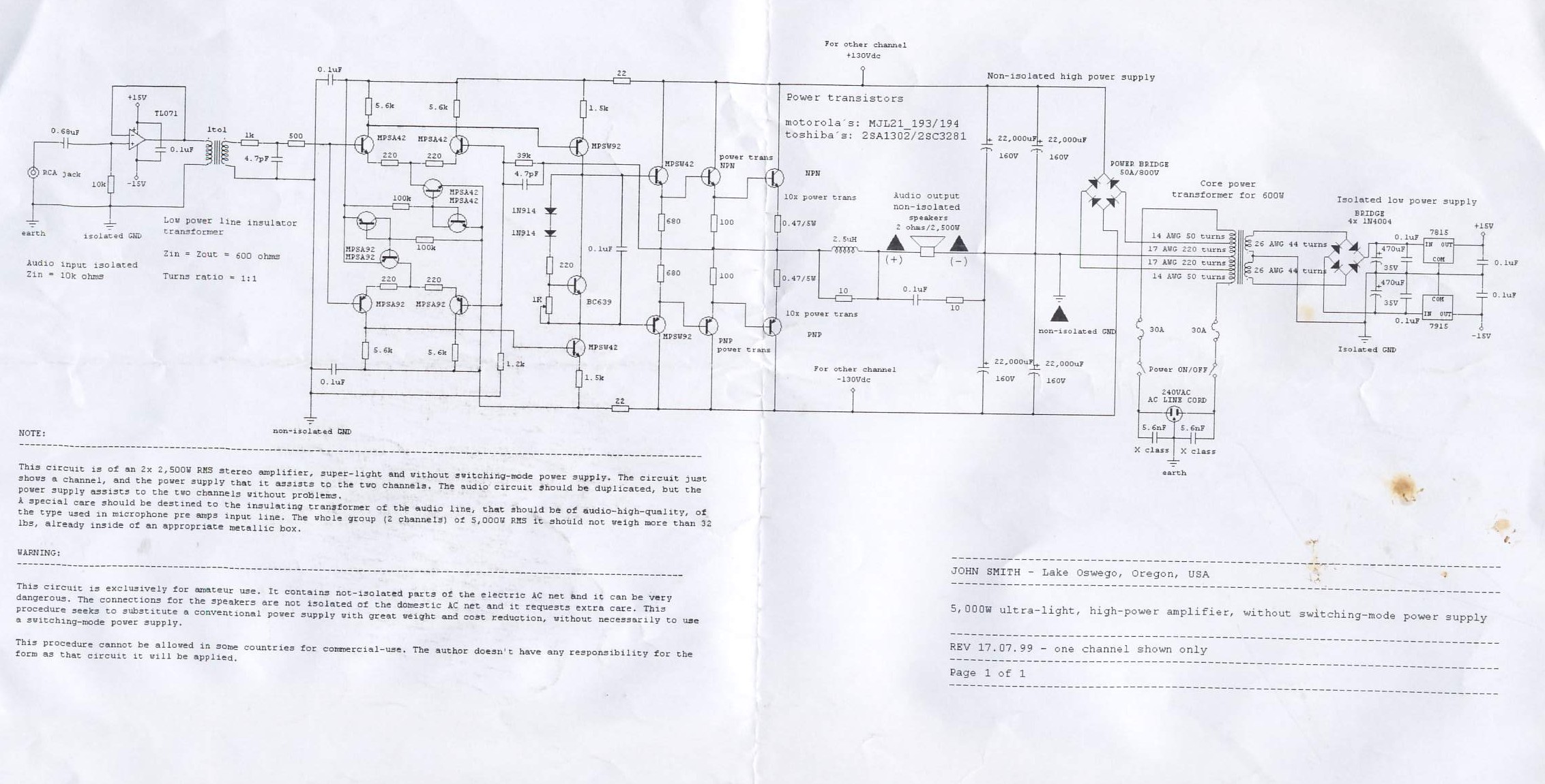
This circuit is for a 2x2, 500W RMS stereo amplifier that is super-light and does not utilize a switching-mode power supply. The circuit diagram displays only one channel, while the power supply is designed to support both channels. The...
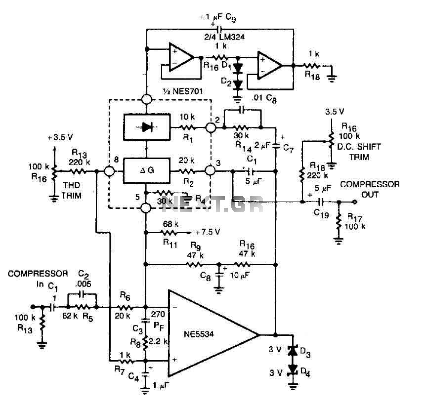
This circuit for a compressor utilizes a high-fidelity external operational amplifier (op amp) with high gain and wide bandwidth. A compensation network at the input is required for stability. The rectifier capacitor (Cg) is not grounded; instead, it is...
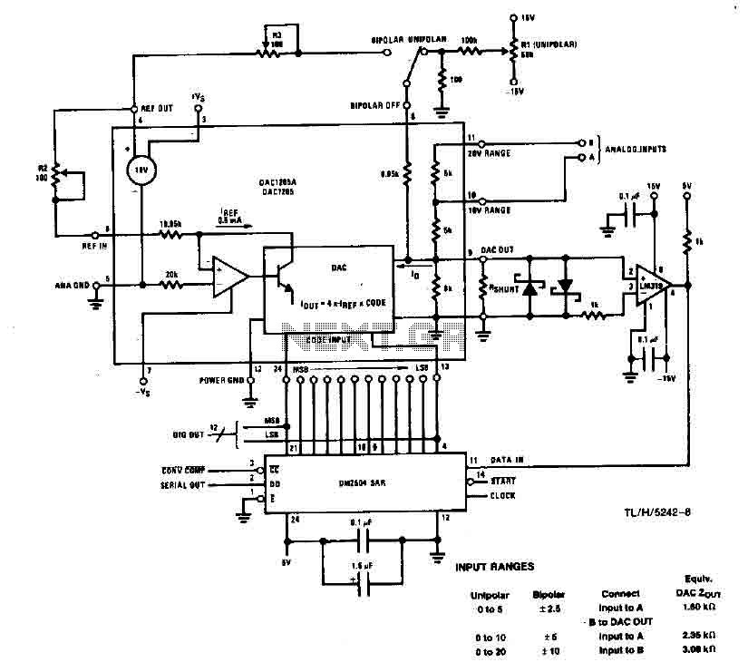
This system performs a complete conversion of 12 bits in both unipolar and bipolar modes. The converter is accurate to ±12-bit LSB with a typical gain temperature coefficient of 10 ppm/°C. In unipolar mode, the system operates within a...
The LTC3731H is a linear three-phase step-down voltage regulation power control unit from the company, capable of driving N-channel MOSFETs. It operates within a temperature range of up to 140°C and supports a control frequency of up to 600...