
forester: window regulator to all the way down to install it
There is no specific limit switch; if the motor is removed, it should run in either direction by reversing the power supply. The motor will stop when it reaches the end of its travel due to increased current draw. Binding was tested with both the old and new motors removed from the door and regulator, resulting in gear rotation only in the "down" direction. Voltage measurements to the motor indicated 12 volts with reversed polarity depending on the switch position, which is expected, but the inability of the motor to reverse direction remains unclear. Disassembly of the old motor revealed a chip in line with one motor connection, which likely failed, preventing power in one direction. An ohmmeter reading confirmed that the chip allowed current flow in only one direction. It is assumed that this chip senses current, and if window movement is obstructed, causing high current, it would temporarily shut down. The motor's function is acknowledged, with a reminder to load check the output from the switch using a headlamp bulb or similar load to ensure sufficient current flow. If a load such as a headlamp can illuminate, it confirms adequate power to operate the motor. The mechanical installation has been successfully completed, and the window has been fully lowered. The provided schematics are being utilized to diagnose why there is only 12 volts available to move the window down and 0 volts to move it up. An open return (ground) is suspected when the switch is pressed to raise the window.
For the electronic schematic description, the system comprises a window regulator motor, a switch assembly, and a power supply. The window motor operates on a 12V DC supply, with control provided through a switch that alters the polarity to dictate the direction of motor rotation. The motor is mounted to a regulator assembly, which is responsible for guiding the window's vertical movement.
The switch is designed to connect the motor to the power supply, allowing the user to control the window's position. When the switch is activated to lower the window, the motor receives power in one direction, causing the regulator to pull the window down. Conversely, when the switch is activated to raise the window, the motor should receive power in the opposite direction.
The schematic should include a representation of the motor with its terminals, the switch with its corresponding connections, and any protective components, such as fuses or diodes, that may be included to prevent back EMF from damaging the circuit when the motor is switched off. Additionally, the power supply should be depicted, showing the voltage source and ground connections, which are critical for the proper operation of the motor.
In troubleshooting, it is essential to verify the continuity of the switch and the integrity of the wiring to ensure that there are no breaks or high-resistance points that could impede current flow. The presence of a load during testing can help confirm that the circuit is functioning as expected, and any abnormal readings should prompt further investigation into the motor's condition and the associated circuitry.It is best to remove the glass from the regulator so that you can move the regulator freely then attach the glass after you install the motor. Once you have the motor installed operate the regulator with the motor to position the glass attachment points where you can reach them.
The guide channel can be slid by hand. Be sure the "foot" of the regulator slides freely in the guide channel The glass is not the problem, yet as it is lying elsewhere in the garage. I have replaced the motor with the regulator in the full up position and have inserted the assembly into the door but I am having trouble alligning the 4 holes to mount the motor to the door panel. I am thinking that maybe the regulator must be in the full down position to align the motor mount. It is easiest to mount the motor in the mid position so that you can rotate the motor. In the full down position the X portion is at the end of its travel and is the full up position is is the same problem.
The lower guide channel can be removed to allow the regulator to rotate to the correct position to match the motor. Be sure you are not trying to mount the motor upside down (don`t laugh I have seen it tried) I will connect the motor to the switch while the assembly is in the door then cause the motor to lower the regulator to the mid position then get back to you.
On a related note what would prevent the window from rising but still allow the window to lower I swapped the door switches but that did not work. However, I measured the voltage to the motor and it is either plus or minus depending on the switch position, something I (electrical engineer, would expect but the motor only turns in one direction.
Is there a stop limit sensor that is indicating the window is ALWAYS full up and preventing the window from closing Thanks for your help. There is not a limit switch per se, if you remove the motor you should be able to run it in either direction by reversing the power supply.
The motor will stop running when it reaches the end of its travel due to the increased current draw. As for binding, I tested the old and new motor with the motor removed from the door and the regulator and only got gear rotation in the "down" direction. I measured the voltage to the motor and got 12 volts with the polarity reversing with change in switch position.
That made sense but not having the motor reverse direction is a mystery. When I broke apart the old motor I found a chip in line with one connection to the motor and I am guessing this went bad preventing the power to the motor in one direction. An ohm meter reading confirmed that the chip was allowing current flow in only one direction. I assumed this chip senses current and if there is something blocking window movement causing high current it would shut down for a short time.
You are correct in the function of the motor. Remember to load check the output from the switch with a headlamp bulb or something that will load the circuit you may have a point of high resistance that is preventing enough current flow in one polariaty. If you can light a load such as a headlamp you can be sure you have enough power to run the motor. I was successful at completing the mechanical installation and have lowered the window fully. I am using the schematics you provided (THANK YOU VERY MUCH!) to see why I now only get 12 volts to move the window down but 0 volts to move it up.
I suspect there may be an open return (ground) when I press the switch to go up. Ask-a-doc Web sites: If you`ve got a quick question, you can try to get an answer from sites that say they have various specialists on hand to give quick answers. Justanswer. com. Traffic on JustAnswer rose 14 percent. and had nearly 400, 000 page views in 30 days. inquiries related to stress, high blood pressure, drinking and heart pain jumped 33 percent. 🔗 External reference
Related Circuits
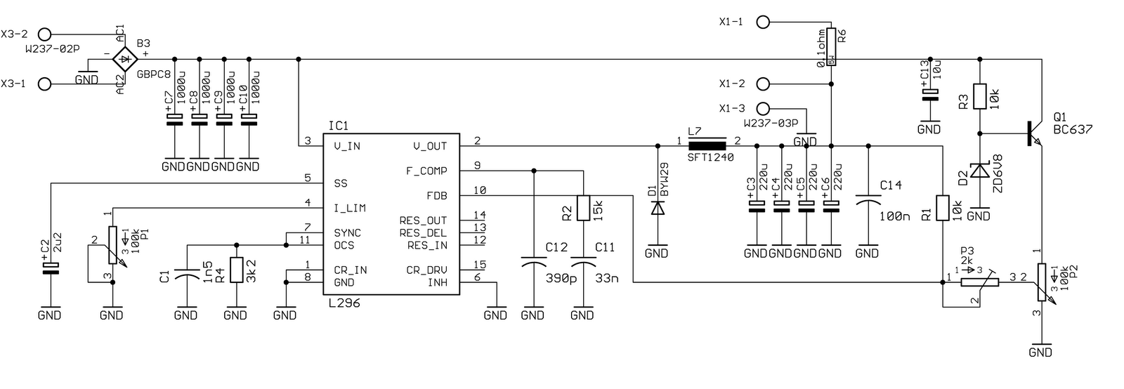
Specifically for the chip used in this circuit, the data is as follows: The oscillator operates at a frequency of 200 kHz, with output noise below 1% (worst case). The maximum current is 4 A at 20 V. The...
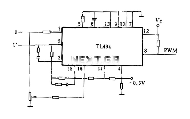
A double-loop speed control system for a brushless DC motor is presented, where the speed controller outputs a torque (or current) signal. The TL494 can be utilized as a current regulator and current limiter. Current feedback is detected from...
The LA1061M is an antenna switching controller designed for mobile radio equipment. It utilizes several inputs from the receiver circuitry to choose between the main antenna and a sub-antenna based on signal strength and quality. Weak and strong signals...

The AT89C51-12PI is a variant of the AT89C51 microcontroller. For further details, please refer to the AT89C51 description. The datasheet for the AT89C51-12PI can be downloaded from the link provided below. This component is produced by ATMEL Corporation. The AT89C51-12PI...

This design circuit is a tone control circuit that utilizes the popular Baxandall configuration, a straightforward circuit layout that allows for continuous boost and cut control. The circuit is inexpensive to construct and is frequently implemented in commercial products....
The output of this circuit is push-pull and consumes less than 3 mA (with no signal) but drives the earpiece to a very loud level when audio is detected. This circuit operates in a push-pull configuration, which allows it to...