
Four channel mixer

The high-gain operational amplifier (op-amp) circuit is designed to amplify multiple input signals while maintaining signal integrity and minimizing noise. This circuit is particularly useful in applications where signal processing from various sources is required, such as audio mixing or sensor data acquisition.
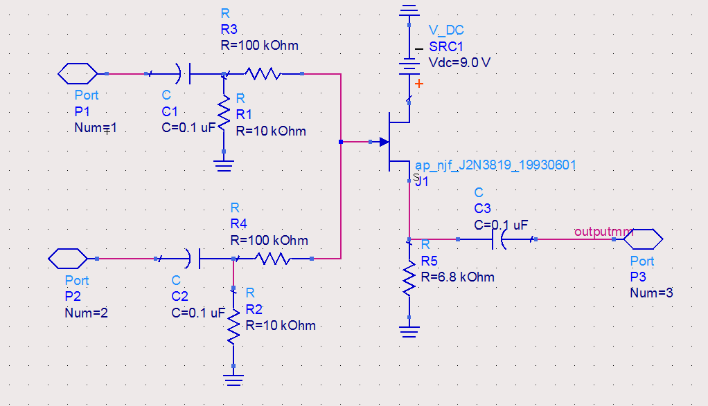
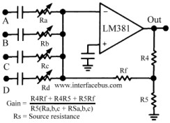
The op-amp configuration allows for the combination of up to four input signals, each of which can be controlled independently. This can be achieved using a combination of resistors and potentiometers to adjust the gain and balance of each input signal before they are fed into the op-amp. The selection of the op-amp itself is critical; a low-noise, high-gain op-amp is recommended to ensure that the amplification is effective without introducing significant distortion or noise.
To ensure optimal performance, the DC power source should be well-filtered. A battery is preferred due to its low noise characteristics, which help to minimize interference in sensitive applications. If using a power supply, it should include adequate filtering components, such as capacitors and inductors, to reduce ripple and noise.
Additionally, the circuit layout must prioritize shielding to prevent electromagnetic interference (EMI) and radio frequency interference (RFI) from affecting the signal. This can be accomplished by using a metal enclosure or incorporating shielding techniques in the PCB design, such as ground planes and careful routing of signal traces.
Overall, the design of a high-gain op-amp circuit that combines multiple input signals requires careful consideration of component selection, power supply filtering, and shielding techniques to ensure high fidelity and reliable performance in various applications.High gain op amp combines up to four individually controlled input signals The dc power source should be well filtered (battery is ideal), and the circuit should be well shielded to prevent hum pickup.
Related Circuits
The circuit utilized was primarily designed for audio mixing, featuring inputs from both a triangular wave generator and a noise generator. These signals are processed through an audio mixer to create the final output wave. This audio mixing circuit integrates...
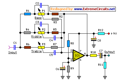
High-quality modular design, powered by a 9V battery, with very low current consumption. The objective of this project was to design a small, portable mixer. The project focuses on creating a compact audio mixer that operates efficiently on a 9V...
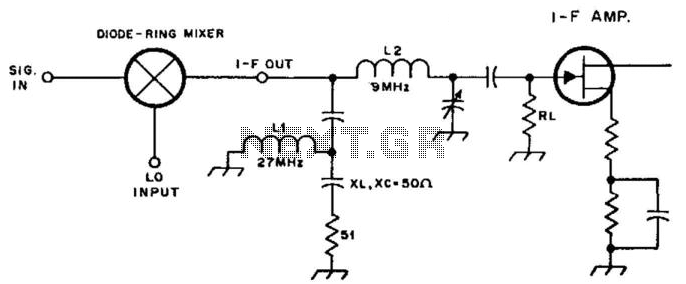
By inserting a high-pass filter section in the intermediate frequency (IF) lead, this mixer is terminated at all frequencies except for the IF, which results in improved intermodulation distortion (IMD) for other mixer products. In this example, the high-pass...
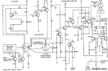
The timing interval is initiated by applying power and is determined by RT-CT. At the end of the interval, a unijunction transistor triggers a silicon-controlled rectifier to apply nearly the full supply voltage to the load. The delay range...
The first prototype PCB has been completed, but concerns arise regarding the heat generated when utilizing the BMS at maximum power in an ultralight hybrid electric vehicle application. At 30A continuous and 50A burst, nearly 20W of loss occurs....
The circuit schematic below represents a method for designing an audio mixer. The active component is an LM318, although any operational amplifier could be used in its place. The circuit is a classic design for an operational amplifier summing...