
Four Foot Box Loop Antenna

The described antenna is a four-foot unamplified box loop designed for receiving signals across the entire AM broadcast band, specifically from 525 kHz to 1710 kHz. The loop antenna is a highly effective design favored by amateur radio enthusiasts (DX'ers) for its ability to nullify interference and enhance the reception of weak signals.
The construction of the antenna minimizes the use of metal hardware. This design choice is critical as it helps maintain a clean radiation pattern, which is essential for effective signal reception. The absence of excessive metal components reduces unwanted reflections and distortions, allowing for a more focused and directional reception. This is particularly advantageous in environments with significant electromagnetic interference.
The antenna is supported by an umbrella stand, which provides stability while remaining lightweight and portable. Filling the stand with sand enhances its stability, preventing tipping or movement due to wind or other external forces. This feature is crucial for outdoor use, where environmental factors can impact performance.
The loop itself is constructed to form a closed circuit, which is effective at capturing electromagnetic waves. The size of the loop, in this case, four feet, is optimized for the frequency range of interest, providing a balance between size and performance. The loop's design allows it to be tuned across the entire broadcast band, making it versatile for various listening applications.
Overall, this unamplified box loop antenna exemplifies a thoughtful approach to amateur radio design, focusing on simplicity, effectiveness, and user-friendly construction. It is suitable for both novice and experienced radio enthusiasts looking to improve their reception capabilities in the AM band.Please find attached your copy of my four foot unampilfied box loop. It will tune from 525 kHz to about 1710 kHz covering the entire Broadcast Band. The umbrella stand described in the article is the type you would use for an outdoor umbrella. I fill mine with sand to keep it sturdy You will also notice a lack of metal hardware in this design. This was done on purpose to keep the antenna`s pattern as clean as possible. Other designs you may see have a lot of metal in them and this will lower their ability to null and to pick up weak signals. This is a DX`er`s loop. If you wish 🔗 External reference
Related Circuits
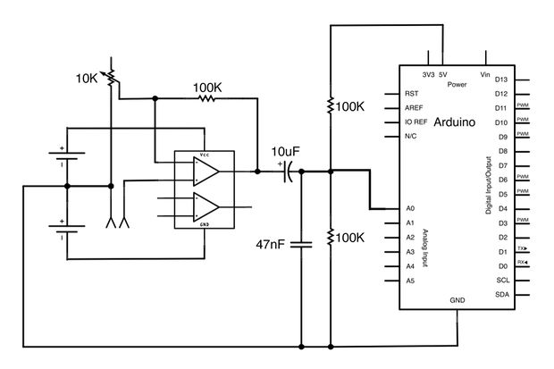
This Arduino-powered vocal effects box pitch shifts and distorts incoming audio signals to produce a wide variety of vocal effects. This project serves as an experiment with real-time digital signal processing using Arduino. It samples an incoming microphone signal...
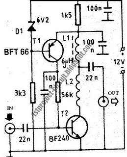
This design presents a simple antenna amplifier electronic circuit project, which can be utilized based on the provided circuit diagram. The antenna amplifier operates effectively within a frequency range of 1 to 300 MHz. It is suitable for high...
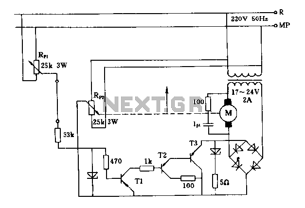
The FIG potentiometer RP2 has a sliding contact that is directly connected to the antenna. The system operates such that only when potentiometers RP1 and RP2 are positioned identically, do the non-conductive transistors and rectifier bridge remain off, resulting...
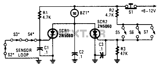
Two SCRs are utilized with two sensor loops. One loop employs series switches, while the other loop employs parallel switches. When a switch is actuated, the SCR is triggered. The alarm is designed to be a non-interrupting type. The circuit...
This is a 4 mA to 20 mA current loop circuit. This circuit is used to transmit a signal over long distances. The accuracy of this circuit is not compromised. The 4 mA to 20 mA current loop circuit is...
Both versions have the schematic attached. However, the resolution of the schematic is not very high. It is advisable to save the image above or download it to ensure accurate visibility of all details. There is no straightforward method...