
TMP01 4 to 20mA Current Loop

The 4 mA to 20 mA current loop circuit is a standard in industrial applications for transmitting sensor signals over long distances, commonly used in process control and automation. The circuit operates by varying the current between 4 mA and 20 mA, where 4 mA typically represents the lowest measurement of a variable (e.g., temperature, pressure) and 20 mA represents the highest. This current loop is particularly advantageous in minimizing the effects of noise and voltage drops over long cable runs, ensuring that the signal remains accurate and reliable.
The circuit typically consists of a current source, a sensor, and a load, which could be a display, a controller, or a data acquisition system. The current source is often implemented using an operational amplifier configured to maintain a constant current, regardless of the load impedance. The sensor generates a voltage proportional to the measured variable, which is then converted into a current signal by the operational amplifier.
In practice, the circuit may include additional components such as resistors for setting the gain of the operational amplifier, capacitors for filtering noise, and diodes for protection against reverse polarity. The use of twisted-pair cables is recommended to further reduce electromagnetic interference, enhancing the integrity of the signal during transmission.
The 4 mA to 20 mA current loop is favored for its simplicity and robustness, allowing for long-distance communication without significant loss of signal integrity, making it a preferred choice in various industrial monitoring and control systems.This is a 4 mA TO 20 mA CURRENT LOOP circuit. This circuit is used to transmit a signal over long distances. The accuracy of this circuit is not compromised.. 🔗 External reference
Related Circuits
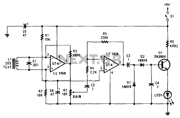
This circuit utilizes a dual operational amplifier to drive a rectifier and emitter-follower configuration, which indicates AC current on an LED. The inductor L1 is formed by a winding of a audio transformer, created with a pick-up coil consisting...
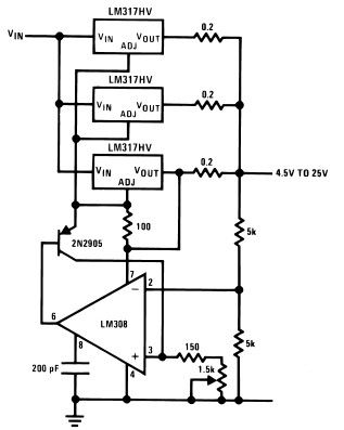
The LM317HV adjustable regulator is capable of supplying over 1.5A across an output voltage range of 1.2V to 57V. The design of this high current power supply is straightforward, as the LM317HV requires only a few external resistors to...
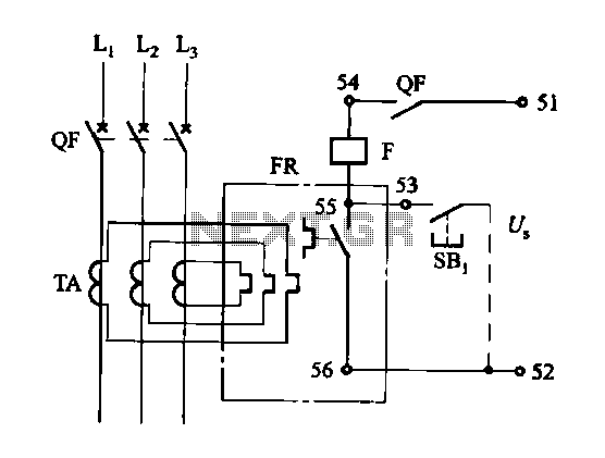
The DK-5A, 5D, and SDb control boxes are equipped with a thermal electromagnetic overcurrent release, as depicted in Figure 6-80. The trip mechanism provides both overload and instantaneous short circuit protection with a long delay feature. In the figure,...
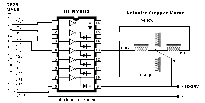
In the search for stepper drivers, the ULN2003 chip was discovered, which facilitates motor operation with minimal circuitry through the parallel port of a PC. However, the current output from the ULN2003 is limited to 500mA, resulting in low...
The current source in the diagram reacts very quickly to changes in the input signal and may be utilized in specific measurements. Differential. The current source depicted in the schematic is designed to provide a stable output current that responds...
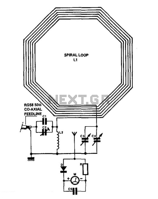
C1 = 3750 pF 500 V silver-mica capacitor. C2 = 100 pF preset capacitor (Jackson C803). C3 = 75 pF variable capacitor (Jackson C809) with a knob. C4 = 12.7 pF variable capacitor (Jackson C16) with a knob. C5...