
Four phase stepper motor drive system

The MAX620 is a high-performance, integrated circuit that functions as a high-side driver, suitable for controlling power MOSFETs in various applications, including stepper motor drives. In this configuration, the device effectively translates low-voltage TTL or CMOS logic signals into higher voltage levels necessary for driving the gate of N-channel MOSFETs. This translation is essential for ensuring that the MOSFETs can fully turn on, allowing efficient current flow to the stepper motor phases.
The four N-channel MOSFETs are arranged in a H-bridge configuration, enabling bidirectional control of the motor phases. This arrangement allows for precise control of the motor's rotation direction and speed by alternating the current flow through the motor windings. Each MOSFET is activated by the output from the MAX620, which is driven by the logic network. This network typically includes a microcontroller or other digital logic devices that generate the control signals based on the desired motor operation.
The inclusion of diodes in the circuit is crucial for protecting the MOSFETs and ensuring reliable operation. When the current through the motor windings is interrupted, the inductive nature of the windings can generate back EMF, which may damage the MOSFETs if not properly managed. The diodes provide a safe path for this discharge current, preventing voltage spikes that could lead to component failure.
Overall, this stepper motor drive configuration utilizing the MAX620 and N-channel MOSFETs offers a robust solution for controlling stepper motors in various applications, providing high efficiency and reliability in operation.A MAX620 connected to form a complete stepper-motor drive. TTL/CMOS signals from the logic network are translated to high-side levels that drive four N-channel power MOSFETs, supplying current to each of four stepper-motor phases. The diodes provide a discharge current path for the stepper-motor windings. MAXIM NEW RELEASES DATA B OOk, 1992, P. 4-28. 🔗 External reference
Related Circuits
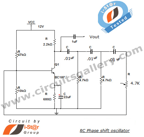
This section introduces a transistor oscillator circuit known as the RC Phase Shift Oscillator. An oscillator is an electronic circuit that functions as a sine wave generator, requiring only a DC power supply. It is commonly used in variable...
The 3D printer necessitates independent control for three separate axes. Each controlled axis must be equipped with a high-precision electronic driver. The mechanical components of each axis utilize a precise bipolar stepper motor connected to a drive shaft via...
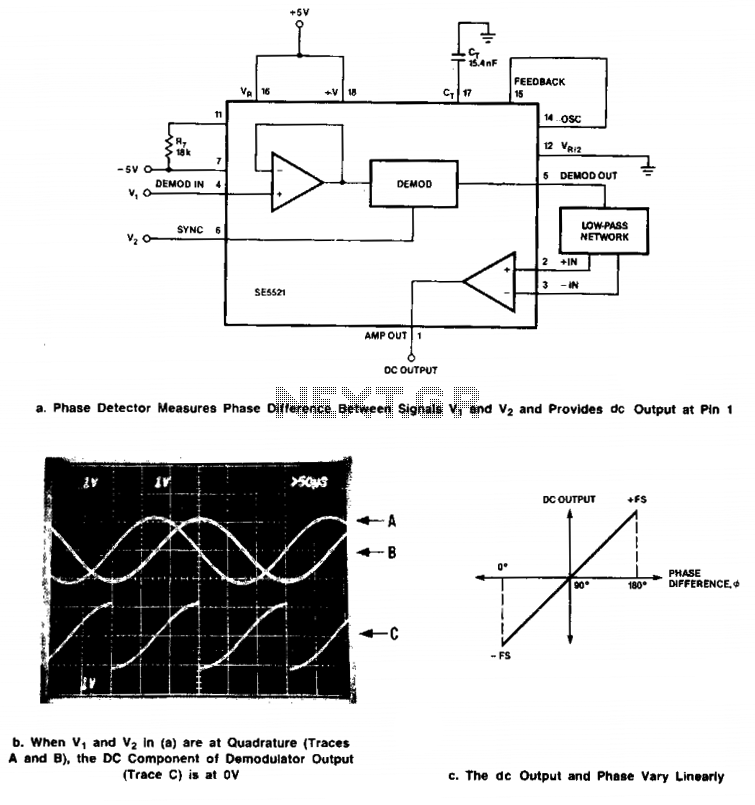
Signals of identical frequency are applied to the sync input (Pin 6) and to the demodulator input (Pin 4). The demodulator operates as a phase detector, with the output DC component being proportional to the phase difference between the...
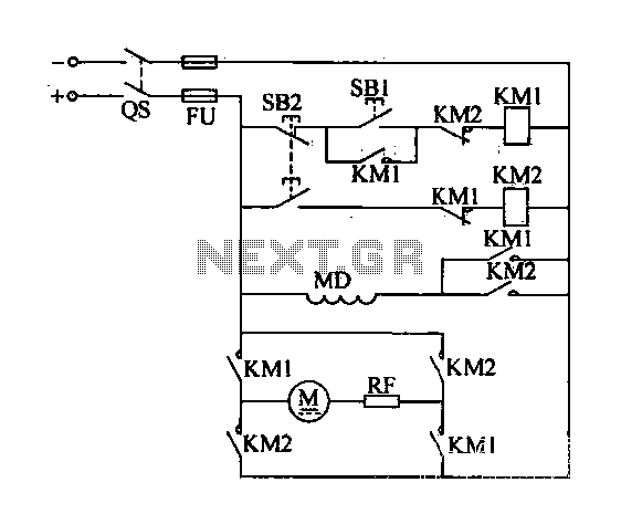
A DC motor reverse brake circuit is presented. To initiate braking, the stop button (SB2) is pressed, which disconnects the move-off contact, causing KM1 to lose power and release. Subsequently, the brake contactor (KM2) is activated. KM2 is designed...
Please find attached your copy of my four foot unamplified box loop. It will tune from 525 kHz to about 1710 kHz covering the entire Broadcast Band. The umbrella stand described in the article is the type you would...

This figure illustrates a block diagram of modern automated systems that incorporate closed-loop feedback for motion control. These systems typically feature a servo system consisting of feedback elements and a motor driver, which work together to provide accurate and...