
INA326 327 a single power PID Proportional - Integral - Derivative temperature control loop circuit

The described circuit is an advanced temperature control system that integrates multiple operational amplifiers to achieve precise temperature regulation through PID control. The thermistor RTHERM plays a critical role in sensing temperature variations and translating these changes into a corresponding electrical signal. This signal is first processed by the INA326/327, which is designed to amplify low-level signals with high accuracy and precision.
The operational amplifier OPA4340 is employed in a dual capacity: first for signal amplification and then for further processing in the PID control loop. The use of three OPA4340 amplifiers allows for a modular approach to scaling, integrating, and differentiating the signal, which is essential for implementing the PID algorithm effectively. The integration of these stages ensures that the control system can react to both instantaneous changes (via the proportional component) and accumulated errors over time (via the integral component), while also considering the rate of change of the error (via the derivative component).
The potentiometers are strategically placed within the circuit to facilitate fine-tuning of the various parameters that govern the PID control process. By adjusting R7, the user can establish a baseline temperature, while R16 allows for the optimization of loop gain, ensuring that the system responds appropriately to deviations from the set point. The adjustments via R17 and R20 further refine the performance of the integrating and differential circuits, contributing to the overall stability and responsiveness of the temperature control loop.
The final output stage, utilizing the OPA2340 as a voltage follower, is critical for maintaining low output impedance, which is necessary for driving subsequent stages or loads without significant signal degradation. This configuration ensures that the PID controller can effectively manage the temperature control system with high reliability and accuracy. As shown by INA326/327 constitute a single power PID (proportional - integral - derivative) as shown in the temperature control loop. The circuit is mainly to complete work on the measurement and control of temperature. RTHERM thermistor temperature detection, the temperature change into an electrical signal input INA326/327, amplified output to the operational amplifier 1/4 (OPA4340) further amplification and adjustment, and then into three operational amplifier 1/4 (OPA4340) scaling circuit integrating circuit, a differentiating circuit (ie PID) consisting of treatment, after the final synthesized by 1/2 (OPA2340) output. Potentiometer R7 for setting the temperature, adjust R7 can RTHERM thermistor temperature at the time of initial output is zero, that is, to determine the initial temperature point.
Potentiometer R16 is used to adjust the loop gain adjustment R16 can make the circuit level to the proportional, integral and differential circuit circuit in the most appropriate value. Potentiometer R17, R20, respectively, adjusted for integrating circuit and applied to the differential input of the circuit level, so that in the most appropriate value.
By a 1/2 (OPA2340) constitute a voltage follower as a bias current generator to provide low-impedance output bias current to each circuit.
Related Circuits
Figure 1 illustrates an AND gate logic circuit with the logic expression P=A. Figure B depicts two photodiodes connected in series. When the input logic levels A=1 and B=1, the output P=1. Similarly, this configuration can be used to...
To extend the measurement range of an available ADC (analog to digital converter), autoranging can be utilized. If implemented on multiplexed input, this... Autoranging is a technique employed in electronic measurement systems to automatically adjust the range of an analog-to-digital...
The MICRF112 is a high-performance, user-friendly, single-chip ASK/FSK transmitter integrated circuit (IC) designed for remote wireless applications within the 300 to 450 MHz frequency band. This transmitter IC features a true data-in, antenna-out configuration. The MICRF112 excels in three...
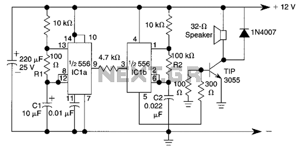
This circuit utilizes a 556 timer IC to initially generate a low-frequency square wave, which is then modulated to produce two alternating tones of approximately 400 Hz and 500 Hz. The circuit is designed to create a warble alarm...
An alternating display for a version 1 nixie clock inspired new logic designs for switching signals to the display. The design eliminated the 4013 flip-flop and two 4017 counters, leading to a redesign of the hours section and reset...
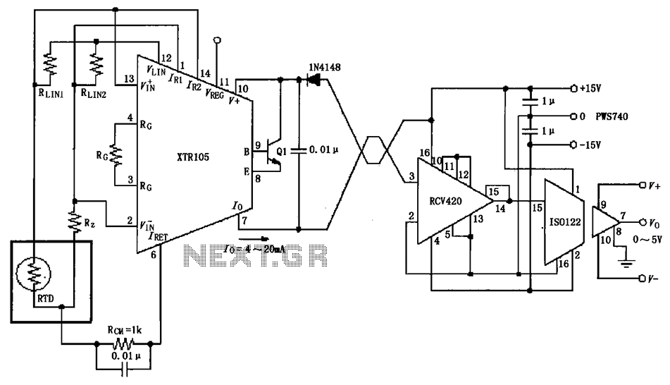
The RTD temperature sensor, as illustrated in the subsequent figure, collects temperature data from the field. This data is converted into a voltage signal by the XTR105, which is then transformed into a 4 to 20 mA current output....