
Radio remote control dimmer circuit

The radio remote control dimmer circuit is designed to provide users with the convenience of remote operation while maintaining efficient control over lighting levels. The core components include a micro radio transmit/receive module, which facilitates wireless communication between the remote control and the dimmer. The light modulation ASIC plays a crucial role in adjusting the brightness of the connected lighting fixture based on the signals received from the remote control.
The circuit's simplicity is one of its key advantages, as it requires only two output wires, which significantly reduces installation complexity compared to traditional dimmer circuits that may require additional wiring for control signals. This two-wire system allows for seamless integration into existing lighting setups without the need for extensive modifications.
In terms of functionality, the remote control allows users to adjust the brightness of the lights from a distance, enhancing user convenience and comfort. The reliability of the circuit ensures consistent performance, making it suitable for various applications, including residential, commercial, and industrial lighting systems. The use of a micro radio module also minimizes interference and ensures stable communication, which is essential for effective dimming control.
Overall, the radio remote control dimmer circuit offers an innovative solution for modern lighting control, combining ease of use, reliability, and efficient design.As shown in the diagram above, it is a radio remote control dimmer circuit. The radio remote control dimmer circuit adopts micro radio transmit/receive module and light modulation ASIC. So the circuit is concise and easy to produce. It works reliably. And the whole switch has only two wires for output.It can directly use it to replace the ordinary lighting..
🔗 External reference
Related Circuits
When a network needs to transfer small blocks of information over long distances, RS-485 is often the preferred interface. Network nodes can include PCs, microcontrollers, or any devices capable of asynchronous serial communications. Compared to Ethernet and other network...
This unit provides 2-way IR communications using a numeric keypad and an LCD display. Data is sent and received in ASCII with no regard to what the data means to any particular device. The ASCII data still needs some...
This 5-volt Switch Mode Power Supply circuit utilizes an integrated circuit (IC) from National Semiconductor, which specializes in the production and design of ICs for switch-mode power supply applications. The 5-volt Switch Mode Power Supply (SMPS) circuit is designed to...
This circuit controls very accurately a fan of any size. Just adjust the associated resistors for a different type like the R6 resistor of 100 ohm, 2 watt type and you're all set. The above circuit diagram is for...
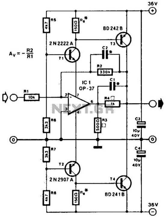
This line driver is capable of driving low-impedance lines with a maximum output of 70 V peak-to-peak. IC1 functions as a low-noise operational amplifier suitable for operation at 15 V. T1 and T2 serve as voltage regulators for the...
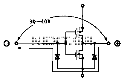
Due to the varying conditions of different input signals, when an abnormal voltage is applied to the pin, protection circuits are designed to create a circuit path that secures the internal protection of large-scale integration (LSI) circuits. The structure...