
Free-Power AM Radio

The described circuit operates as a basic AM radio receiver with a single silicon transistor serving as the amplification element. The architecture employs a common-emitter configuration, which is standard for audio amplification applications. The introduction of a potentiometer allows for dynamic adjustment of the feedback loop, enhancing the ability to tune into specific frequencies while managing the gain.
The feedback mechanism is crucial for achieving a degree of regeneration, which is a characteristic feature of many radio receivers. By adjusting the potentiometer, the user can control how much of the amplified signal is fed back into the antenna coil, which is essential for maintaining oscillation near the tuned frequency. However, due to the limitations of the ambient power source, the circuit operates in a quasi-oscillatory state rather than achieving full oscillation, which results in a distinct audio output characterized by clipping distortion.
The choice of components significantly influences the performance of the receiver. The use of a silicon diode in place of a resistor for the collector load enhances signal strength, demonstrating the importance of component characteristics in circuit design. The reduction of the collector resistor value also illustrates the trade-off between signal volume and power retention, emphasizing the need for careful consideration of component values in low-power applications.
The circuit's ability to function with various audio outputs, including crystal earphones and magnetic headphones, highlights its versatility. However, the inclusion of a blocking capacitor is critical to prevent excessive current draw, which could lead to circuit failure. The findings regarding the performance of germanium versus silicon diodes underscore the necessity for empirical testing in circuit development, as theoretical expectations may not always align with practical results.
Overall, this circuit exemplifies the principles of radio frequency amplification and feedback in a low-power environment, making it a valuable project for enthusiasts interested in crystal radio technology.Here`s something that might intrigue you Crystal Radio builders out there: A one-transistor (Silicon, yet!) AM broadcast receiver that derives its power from ambient AC hum and `spherics [static crashes]! Gotta give credit when I can: The germ of the schematic was borrowed from Darryl Boyd`s "Stay Tuned" website which features over 170 articles an
d plans on crystal radio construction. The URL for the site is and my No-Power - or, more accurately, Free-Power - circuit was derived from #2 of the 3 circuits found in the site`s project #153, "How to Build Free-Power Radios. " That website has three jpeg pages which are copies of the original article, by Terry L. Lyon, from an old Popular Electronics magazine issue. The 2nd page is the page containing the 3 schematics of single-transistor, free-power receivers. My version has some modifications of the original circuit, which I will describe below. Terry Lyons` original circuit was designed around a common-emitter amplifier, with emitter grounded; mine has a 100K ohm potentiometer inserted between the emitter and ground.
The wiper of the pot connects to a tap on the antenna coil, 5 turns up from ground, with the pot determining how much of the emitter current is permitted to flow through the coil winding in a Hartley Oscillator feedback configuration, so that a fraction of the incoming RF signal is fed back into itself after having been boosted by the transistor. With enough battery voltage present, advancing the pot to full clockwise would connect the transistor`s emitter directly to the coil tap, causing the circuit gain to increase through positive feedback (regeneration) until the circuit "plops" into oscillation at the tuned frequency.
In our "free-power" receiver, there isn`t enough voltage or current to achieve stable regeneration to the point of self-oscillation; instead, we get "close": the volume comes up on our radio reception, to a point where we begin to hear a lot of clipping distortion that sounds like "clicks" on voice peaks. If we back the regen ("Sensitivity") control a little, we clarify the sound but lose a little volume.
This is the optimum setting of the Sensitivity control. Your mileage may vary. Lyons` circuits were predicated upon the fact that using a 10 Megohm resistor as the collector load kept the small power supply voltage - the charge accumulated, rectified and stored on the filter cap - from being bled away too fast. He also used a very high value resistor between collector and base. I found out, by trial and error, that using a 1N914 silicon diode in the resistor`s place, gave a louder signal.
Also, I found that reducing the collector resistor from the original 10M (!) down to 470K, gave me quite a bit more sound volume-although it did hasten the bleeding away of accumulated charge. But I found I could live with it. (By the way, I did most of my experimenting with a Radio Shack Amplified Speaker hanging off the audio output.
The crystal (ceramic) earphone I had lying on the bench also worked, as did a pair of stinky old 2000 ohm magnetic headphones. just make sure that the. 47uF blocking cap is in circuit. If you try to connect the magnetic phones directly to the transistors`s collector and ground, the phones bleed the charge away very quickly and you end up with a dead receiver!
I tried using Germanium diodes as rectifiers- and, contrary to what I expected [they have a lower turn-on threshold than Silicon diodes -. 2v vs. . 6v- so I thought they would be more effective than the Silicons. Wrong. They only seem to generate tens of millivolts, whereas Silicon diodes in the same circuit provide a fairly constant 450 - 600 mV.
The circuit can actually be brought close to the edge of oscillation, but this attempts to pull more current than the "atmospheric supply" can deliver, so you will hear a sharp, clicking or rattling distortion rather than plopping into oscillation, when the Regen (Sens 🔗 External reference
Related Circuits
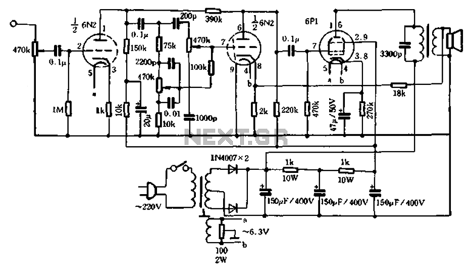
2W resistors can be used with metal or carbon film resistors and optional paper capacitors, polypropylene capacitors, rated for 400V. A selection of different media is available in various configurations. Although there is no established polarity for vintage paper...
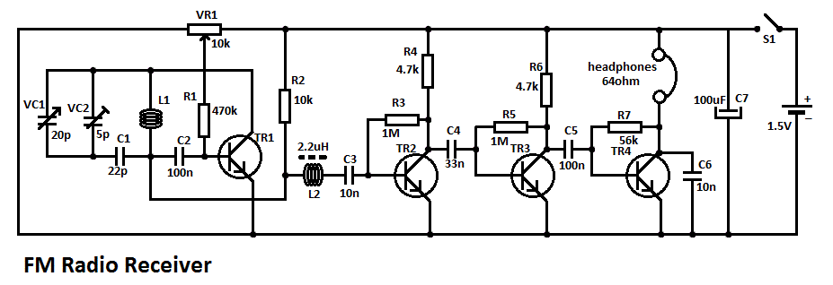
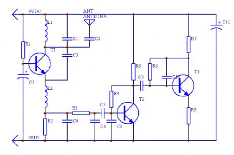
This simple FM radio receiver circuit consists of a regenerative RF stage, TR1, followed by a two or three-stage audio amplifier comprising TR2 to TR4. In some areas... This circuit is designed to receive FM radio signals, utilizing a regenerative...
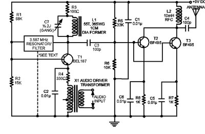
The circuit presented here is a powerful AM transmitter utilizing a ceramic resonator/filter operating at 3.587 MHz. This circuit primarily relies on a transistor for its core functionality. It is possible to use resonators/filters of other frequencies, such as...
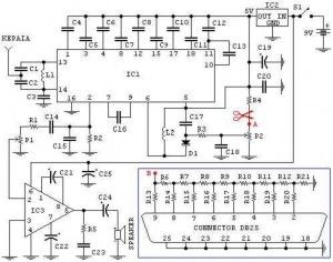
Pictured above is a little AM superhetrodyne receiver that covers the broadcast band from 550 Khz to 1650 Khz. The circuit employs the 8 pin Signetics balanced mixer IC (NE602) which converts the incoming RF signal to the standard...
This is an FM radio receiver circuit that can be used with a PC. The circuit includes several regulations: A) The P1 potentiometer is used to adjust the sound intensity. B) The P2 potentiometer is used to adjust the...
This is a simple RF receiver primarily designed for low-distance digital radio receiver applications. The analog output of this circuit should be connected to a Schmitt-trigger signal conditioning circuit with an appropriate capacitor value (from the collector of T3)....