
Simple light-operated street lamp circuit diagram(3)
")
The circuit involves a photodiode (VDP) functioning as a light sensor, controlling the state of a transistor (VT2) and a thyristor (VT1). During daylight, the low resistance of the photodiode results in VT2 being non-conductive, which in turn ensures that VT1 remains off since there is no gate current to trigger it. Consequently, the emitter (E) does not receive power, thus remaining inactive.
In contrast, during nighttime, the photodiode's resistance increases significantly due to the absence of light, reaching approximately 100 kΩ. This high resistance activates VT2, allowing it to conduct. The activation of VT2 subsequently provides the necessary trigger current to the gate of thyristor VT1, turning it on. When VT1 is triggered, it allows current to flow to the emitter (E), resulting in its activation.
This configuration can be utilized in various applications, such as automatic lighting systems, where the circuit responds to ambient light levels. The transition between day and night conditions is critical for the operation of this circuit, ensuring that the emitter is only powered in low-light conditions. Proper selection of components, such as the photodiode, transistors, and thyristor, is essential to achieve the desired response times and sensitivity to light changes. The circuit may also include additional elements such as resistors for biasing and capacitors for filtering, which can enhance performance and stability.VDP is the photodiode and it has low resistance in the day, and resistance ? 1k?, then transistor VT2 is turned off, then thyristor VT1 is in the off-state as the gate has no trigger current, and E can not be lit. In the night, VL shows a high resistance as no light exposure, and the resistance ? 100k?, then VT2 is turned on, and the emitter can output pos.. 🔗 External reference
Related Circuits
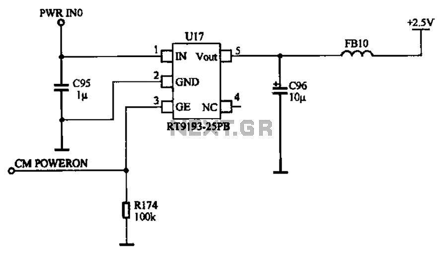
The camera power supply circuit illustrates the essential power supply required for the proper functioning of the camera. This power supply circuit is composed of a stable voltage control integrated circuit. The camera power supply circuit is critical for ensuring...
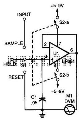
This circuit demonstrates the principle of the sample-and-hold circuit. SI can be replaced by electronic switches (FET, etc.) in an actual application. The sample-and-hold circuit is an essential component in various analog-to-digital conversion applications. Its primary function is to capture...
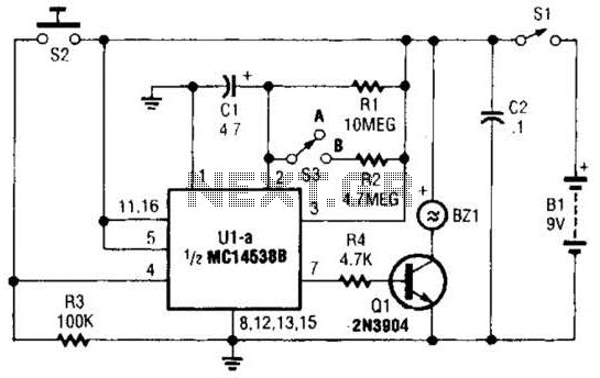
This circuit emits a loud tone if the input switch (S2) is not retriggered at designated intervals. If the user falls asleep and fails to re-trigger the circuit, it will continue to sound until S2 is pressed. The circuit operates...
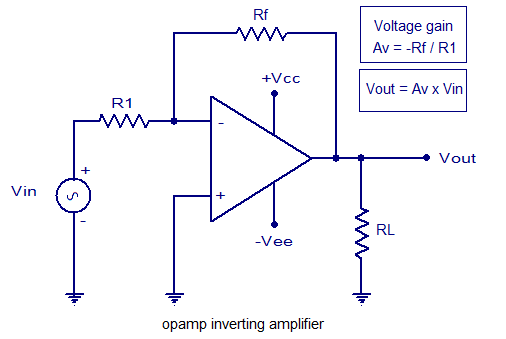
An inverting amplifier utilizing an operational amplifier (op-amp). This includes equations for voltage gain and output voltage, as well as input and output waveforms, and a practical inverting amplifier circuit using the 741 IC. An inverting amplifier is a fundamental...
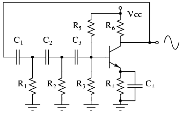
The phase shift oscillator produces a sine wave output in the audio frequency range. Resistive feedback from the collector results in negative feedback due to a 180-degree phase inversion from the base to the collector. The three 60-degree RC...
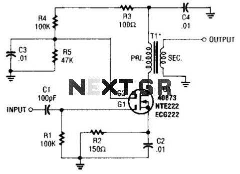
A MOSFET is utilized as a wideband buffer amplifier. T1 is wound on a toroid of approximately specified diameter, using material suitable for the frequency range, typically between 1 MHz and 20 MHz. The turns ratio should be approximately...