
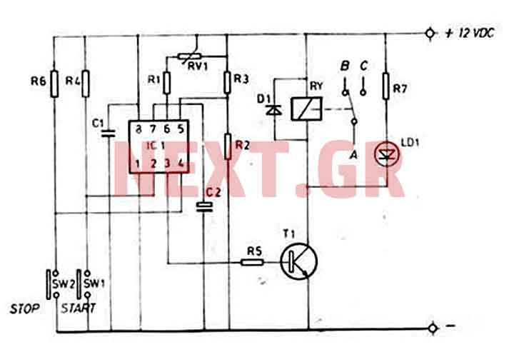
Jogging Timer

The timer circuit utilizes a rotary switch (SW1) to select the desired timing interval. The switch has nine distinct positions, each corresponding to a specific time delay before the piezo sounder emits a series of beeps. The circuit is designed to provide auditory feedback to the user, which can be particularly beneficial during jogging or exercise routines, allowing them to maintain pace or track elapsed time without needing to check a watch or timer.
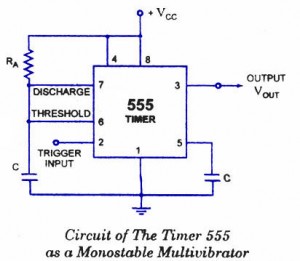
The piezo sounder is an efficient and compact component that converts electrical signals into sound. The circuit may include a timing mechanism, such as a 555 timer IC configured in astable or monostable mode, to generate the precise timing intervals. Capacitors and resistors are likely used in conjunction with the timer IC to set the timing characteristics, determining how long the circuit waits before activating the sounder.
In practical terms, when the user turns the rotary switch to the desired position, the circuit is activated, and the timing sequence begins. The output from the timer triggers the piezo sounder to produce a series of beeps, providing an audible cue at the set intervals. The design is user-friendly, allowing individuals to easily adjust their timing preferences based on their exercise routines. This circuit can be further enhanced with additional features, such as LED indicators or a more complex timing mechanism, to provide greater functionality and versatility for users.This circuit was developed since a number of visitors of this website requested a timer capable of emitting a beep after one, two, three minutes and so on, for jogging purposes. As shown in the Circuit diagram, SW1 is a 1 pole 9 ways Rotary Switch. Setting the switch in position 1, the Piezo sounder emits three short beeps every minute. In positio n 2 the same thing happens after 2 minutes, and so on, reaching a maximum interval of 9 minutes in position 9. 🔗 External reference
Related Circuits
This timer is ideal for small applications. Due to its simple structure, its usage and nevertheless its universal character, this mini timer is usable in the most current applications needing time intervals, from some seconds through approximately 60 minutes....
A very long time constant is provided by R1 and C1. C1 discharges, and the near-zero voltage at its positive lead is applied to the high-impedance inputs of the circuit. In this circuit, the combination of resistor R1 and capacitor...

This 555 timer circuit temperature monitoring system project can monitor temperature at up to four points. The system allows for the selection of whether the alarm should be triggered when the temperature increases or decreases, depending on the resistance...

A project is underway that necessitates the conversion of a 0-10V DC supply into a linear frequency range in the form of a square wave. The project involves designing a circuit that takes a direct current (DC) voltage input ranging...
A monostable multivibrator (MMV), commonly referred to as a one-shot multivibrator, is a pulse generator circuit where the pulse duration is determined by an externally connected resistor-capacitor (R-C) network to a 555 timer. In this configuration, one output state...
A precision circuit utilizing the LM567 timer, specifically the MPI826, where the LM567 functions as a dual-band oscillator. The MP1826 serves as a divider in the circuit, allowing the output signal from the LM567 to achieve extended timing. The...