
Frequency Counter For PC

Please do not ask me to send programmed PICs or even circuit boards to you, my spare time is too short - and you will find anything you need on these "do-it-yourself" pages ! If your counter shows a strange frequency initially, enter setup mode to set the frequency offset to zero (it sometimes happens that PIC programmers don`t erase the EEPROM where the frequency offset is stored).
A flashing decimal point indicates a frequency in kilohertz, a steady point indicates a frequency in Megahertz - which is more common for the intended use in dip meters and QRP transceivers. The circuit diagram is so simple that I didn`t make a complete Eagle schematic for it yet (other builders did, see links ).
The first prototype was built on a breadboard with round pads. A very similar design could be used for a single-sided printed circuit board. Four bridges (drawn in red colour below)must be soldered on the board before fitting the seven-segment displays. Note that the crystal is mounted on the bottom side ! Some of the display signal are routed with thin enamelled copper wire, especially those between two pads.
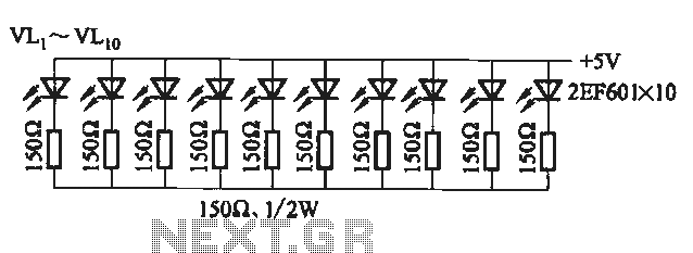
The resistors R4. R11 set the brightness and the power consumption. If you find some suitable low-current displays, use 1 kOhm or even more. Very old displays require more current, use 390 Ohms in that case. The PIC`s output ports can source and sink 20 mA per pin, so the digit drivers are a slightly overloaded with 390 Ohm resistors per segment when displaying "8. ". If you don`t have to care for power consumption and want to use old displays with high current, use four PNP (!) transistors in the cathode(!) drivers as non-inverting emitter followers, no base resistors are required (base to PIC, collector to ground, emitter to common cathode).
For the displays "SC39-11SRWA" by Kingbright it is unnecessary to use driver transistors, these high-efficiency displaye are bright enough with 1 kOhm current limiting resistor per segment. In you can -or, at least, could-order these displays at Reichelt, look for "SC 39-11 RT"in their catalogue (in fact, these used to be SC39-11SRWA displays; aka "super bright" / high-efficiency display.
Do NOT use the low-efficiency types like SC39-EWA. You will be disappointed by a dark display, at least with the resistor values stated above). For the second prototype, a 5-digit display was made on a single layer PCB shown below. The segment resistors were used to connect the display board with the PIC board (which is usually mounted in a 90 ° angle behind the display). To make connection between PIC and display board easier, a second firmware variant was created with slightly modified pin assignment.
On this occasion, the PIC`s clock frequency was increased to 20 MHz to have a better resolution at higher frequencies. Component values for variant 2 (as shown above): R1. R8 = 1k, R9=R10=10k, D1. D4=1N4148, T1=BC547 or similar, C1=C2 about 22pF (select them to tune the crystal to exactly 20 MHz), C3=100nF, Q1=20 MHz, PIC: 16F628 programmed with firmware "counter2.
hex". Layout of the PIC board (display variant 2). The board contains the decoder for the 5th digit, and some breadboard area for the preamplifier (if needed). Print this image with exactly 300dpi, which can be achieved with IrfanView and other utilities. The display is mounted on the lower side of the PIC board as shown below. The square pads near the display are the cathode connectors (from left to right: d1. d4 are outputs directly from the PIC, d5 is driven by transistor T1). Placement of the components on the PIC board (Ridiculously simple, isn`t it But don`t forget to place the bridge under the PIC socket bef
🔗 External reference
Related Circuits
A 0 to 2 MHz frequency meter with a Minimum Mass Wireless Coupler, based on the ATMega8. Range to the Minimum Mass Base Unit is 10 to 15 cm. Since the frequency meter is battery operated, it can be...
The circuit utilizes a 555 timer configured as a multivibrator, where the oscillation frequency is determined by resistors R1, R2, and capacitor C1. The frequency formula is given by fo = 1.443 / ((R1 + R2) * C1). The...
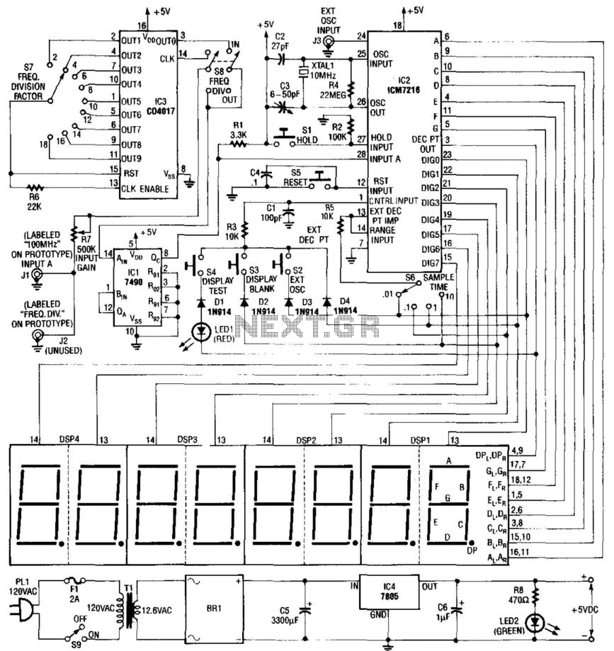
Built around an Intersil 7216 frequency counter IC, this counter has a basic range of 10 MHz, a 100-MHz prescaler, and an extra frequency divider (IC3). This divider reduces the frequency by an additional factor, as indicated on S7...
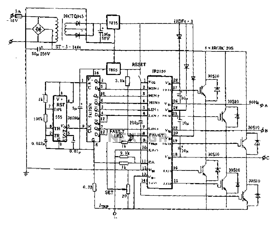
The application of the aforementioned advantages allows the IR2130 to be effectively utilized for DC cut crossing speed, DC servo systems, three-phase power inverters, and switching power supplies. Additionally, it is applicable in inverter power supplies, uninterruptible power supplies...
This project measures the clock pulses supplied to the Timer input of the AVR microcontroller. The Bascom code counts the clock pulses over a duration of 1 second and displays the result. The circuit for this project primarily consists of...
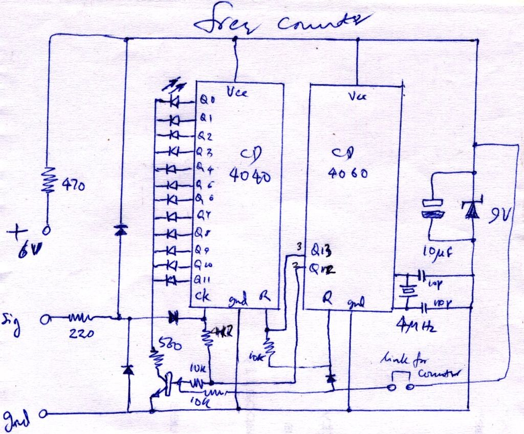
The construction is nearly complete, and a circuit diagram has been created. The design has been finalized and documented on paper. The circuit diagram represents a critical stage in the development of an electronic project, serving as a blueprint for...