
Frequency Counter Schematic diagram

The ATmega328P-PU microcontroller is an 8-bit AVR microcontroller that operates at a clock speed of up to 20 MHz. It features 32 general-purpose I/O pins, 23 of which can be configured as analog inputs. This microcontroller is widely used in various applications due to its versatility and ease of programming, often utilized in Arduino-based projects. The microcontroller requires a stable voltage supply, typically 5V, which can be achieved using a voltage regulator if necessary.
The LCD display commonly used in conjunction with the ATmega328P is typically a 16x2 character display, which can show two lines of 16 characters each. This display operates at a voltage of 5V and communicates with the microcontroller using either a parallel or serial interface. The parallel interface requires multiple I/O pins for data transmission, while the serial interface, such as I2C, reduces the number of pins needed, allowing for easier integration into the design.
In the schematic, the power supply circuit must be designed to provide a consistent 5V output to both the ATmega328P and the LCD. Capacitors may be included to filter out noise and stabilize the voltage. Additionally, pull-up resistors may be required for I2C communication if that interface is chosen. The connections between the microcontroller and the LCD must be clearly defined, ensuring that data pins, control pins, and power connections are appropriately mapped.
Overall, the design should emphasize the importance of stable power and proper interfacing between the microcontroller and the LCD to ensure reliable operation.As you can see, there are few parts to this design, really just the ATmega328p-pu microcontroller and the LCD display. Both of them require a steady +.. 🔗 External reference
Related Circuits
This is a clap switch designed to avoid false triggering. To activate or deactivate any appliance, a user must clap twice. The circuit changes its output state only when two claps are detected within a specified time frame of...

The circuit depicted in the figure is based on the RF2126, a 2450 MHz end-stage linear power amplifier. The radio frequency (RF) signal enters through input pin 1 and is subsequently amplified by the amplifier stages (pins 5, 6,...
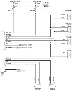
The following document provides a comprehensive car wiring diagram for the 1994 Mazda 626. It includes diagrams for the 2.0L and 2.5L engine configurations, covering the A/C circuit, heater circuit, anti-lock brake circuits, and anti-theft circuit. The wiring schematic for...
Electronic circuits are presented in schematic form. A schematic is essentially a map that illustrates the path of current through various components. Each component is represented by a symbol, typically accompanied by a label or a value, or both....

Often, the frequency of a signal must be doubled, and the modulator/demodulator chip LM1496 serves as an ideal basis for this application. From trigonometry, it is well known that 2sin(x)cos(x) = sin(2x) and sin^2(x) = 1 - cos^2(x). These...
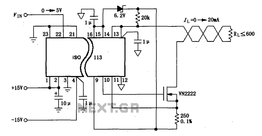
The circuit depicted in the figure consists of an ISO113 current loop isolation drive circuit that operates with an input signal (VIN) to provide an isolated amplified output of 0 to 20 mA. This current is transmitted to the...