
Frequency Generator circuit

The circuit described is a frequency generation system designed for workshop applications, featuring a high-precision oscillator and a frequency divider. The oscillator is based around a 1 MHz crystal (Q1), which serves as the frequency-determining element, ensuring stable and accurate frequency output. The circuit's primary function is to generate a basic frequency and subsequently divide it by a factor of 10 to produce a lower frequency output.
The oscillator is configured using passive components, including resistors (R1, R2-8, R9, R10) and capacitors (C1-2, C3). Resistor R1, valued at 1 MΩ, is likely used to set the gain of the oscillator stage, while R2-8, at 100 Ω, serves as part of the feedback loop to stabilize the oscillation. The capacitors C1-2 (27 pF ceramic) and C3 (100 nF, 100V MKT) are used for tuning the oscillator circuit and filtering, respectively, ensuring that the output signal maintains its integrity and desired shape.
The frequency divider is implemented with an integrated circuit (IC1), specifically the 4584, which is a quad Schmitt trigger oscillator. This IC allows for the precise division of the frequency generated by the oscillator. The output from the oscillator is fed into the frequency divider, which produces a square wave output that is 1/10th the frequency of the input signal. This division is crucial for applications requiring lower frequency signals.
The circuit also incorporates a transistor (TR1), specifically a BC337, which functions as a switching element, allowing the output to drive a load, such as an LED (D1, a red LED), indicating the status of the output signal. The use of a 33 kΩ resistor (R9) in conjunction with the transistor helps to limit the current and protect the LED from excessive current flow.
Overall, the described circuit is a compact and efficient frequency generator and divider, suitable for various applications in workshops where precise frequency control is required. The quadrangular pulses produced by this circuit can be utilized in timing applications, signal generation, or as a clock source for digital circuits.This is a useful instrument for works hops. The standard of the produced frequencies is 10 to 1. The basic frequency is produced by a crystal with high accuracy. The circuit is consisted by the oscillator, around the crystal and the frequency divider, which divides to 10. The produced pulses are quadrangular. R1= 1 Mohms C1-2= 27pF ceramic Q1=1 MHZ Crystal R2-8= 100 ohms C3= 100nF 100V MKT D1= RED LED R9= 33K ohms IC1= 4584 TR1= BC337 R10= 1.5Kohms IC2-7= 4017 🔗 External reference
Related Circuits
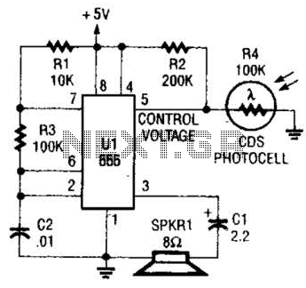
This circuit can be utilized as a light detector and potentially as a tool for individuals with visual impairments. The frequency of the oscillator is influenced by the level of illumination received by LDR4. The circuit operates by employing a...
Nowadays, an increasing number of audio-visual devices in homes are interconnected. This is particularly true for televisions, which may be linked to DVD players. In modern home entertainment systems, the integration of various audio-visual devices enhances user experience and convenience....

An innovative current detection method eliminates the power loss associated with the sense resistor in series with the motor. A 4-digit analog converter (DAC) facilitates digital control of the motor current path, simplifying the implementation of full, half, and...
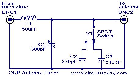
Low power (3 to 30 MHz) transmitters constructed by amateur radio operators are commonly referred to as QRP transmitters. A well-tuned antenna is essential for these transmitters; if the impedance is not properly matched, the output will be minimal...
The project involves the development of a miniature transmitter suitable for implantation in a rat's body, capable of transmitting 416-bit data samples at a rate of 400 samples per second. It is designed to have a detection range of...
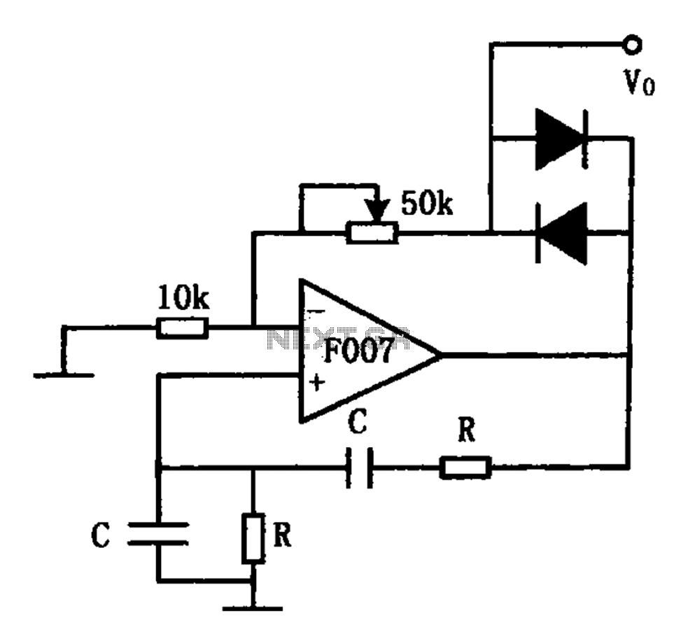
The stable sine wave oscillator circuit is designed to maintain consistent oscillation. The loop gain must be carefully managed; if the gain is excessive, waveform distortion occurs, while insufficient gain can lead to cessation of oscillation. This circuit employs...