
Frequency Meter Circuit

The frequency meter circuit is designed to accurately measure and display frequency across various amateur radio bands, specifically HF (High Frequency), VHF (Very High Frequency), and UHF (Ultra High Frequency). The circuit utilizes a microcontroller or dedicated frequency counter IC to process the incoming signal and convert it into a readable format.
The input stage typically consists of an RF front end, which may include a low-noise amplifier (LNA) to boost weak signals and a bandpass filter to isolate the desired frequency range from unwanted signals. The filtered signal is then fed into the frequency counter, which counts the number of cycles over a defined time period, allowing it to determine the frequency of the incoming signal accurately.
To display the measured frequency, an LCD screen is employed. The microcontroller processes the frequency data and formats it for output to the LCD. The display is designed to show the frequency in a user-friendly manner, often with options for different units (such as MHz or kHz) based on the frequency range being measured.
Power supply considerations are also important in this circuit design. A stable voltage source is required to ensure accurate measurements and reliable operation. It is common to use a regulated power supply or battery to provide the necessary voltage levels for the circuit components.
Additional features may include a calibration function to ensure accuracy, a backlight for the LCD for use in low-light conditions, and possibly a user interface with buttons or a rotary encoder for selecting frequency ranges or modes of operation.
Overall, this frequency meter circuit serves as a valuable tool for amateur radio operators and service technicians, allowing them to monitor and troubleshoot communication equipment effectively across multiple frequency bands.Frequency Meter Circuit of Service Include all the standard frequency bands amateur hf and vhf and uhf And displayed on the LCD screen This is to e. 🔗 External reference
Related Circuits
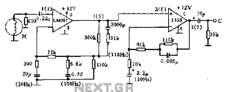
The phonograph pickup head is represented in the schematic as component M, which generates the pick-up signal and is processed through an LM387 amplifier circuit. The LM387 is part of the LM38X series, recognized for its advanced linear amplifier...
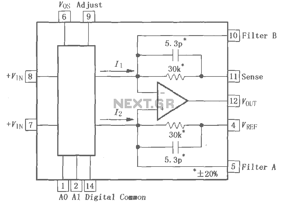
The PGA202 is a digitally controlled programmable gain amplifier with gain settings of G = 1, 10, 100, and 1000. The PGA203 offers gain settings of G = 1, 2, 4, and 8. Both amplifiers are compatible with CMOS...
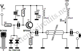
Function: step down the antenna impedance from high to 50 ohms and not, as would be expected, to effect a change from balanced to unbalanced. Component: .. In the context of antenna systems, impedance matching is crucial for maximizing power...
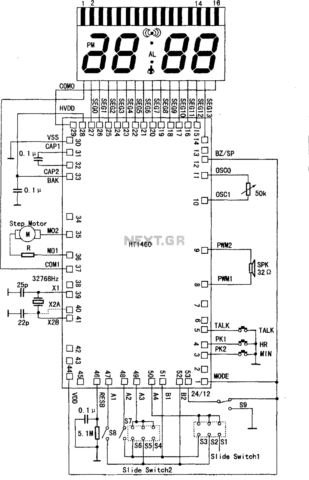
The speech synthesis circuit incorporates a microprocessor series, LCD drivers, a clock oscillator, input and output ports, memory, and a multi-voice audio signal amplifier circuit unit. This series circuit is primarily utilized in voice clocks, thermometers, electronic calendars, and...
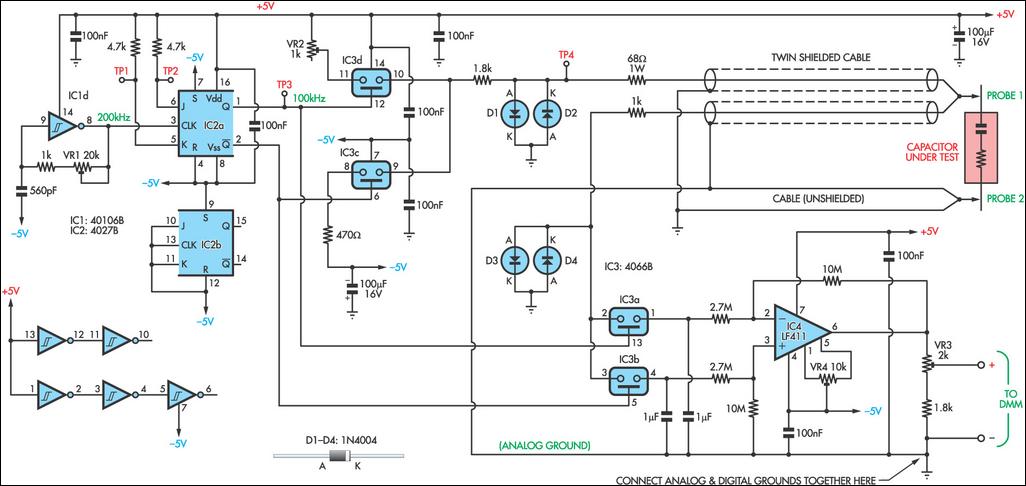
As electrolytic capacitors age, their internal resistance, known as "equivalent series resistance" (ESR), gradually increases, potentially leading to equipment failure. This design allows for the measurement of the ESR of suspect capacitors as well as other small resistances. The...
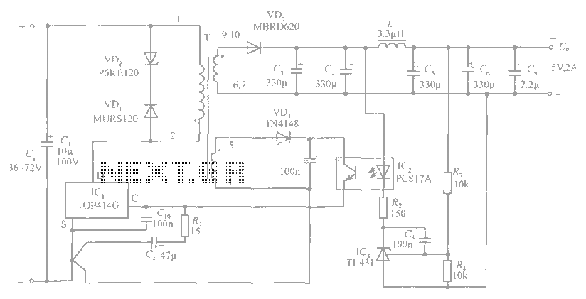
The circuit diagram includes an input filter capacitor C1 and a primary clamp composed of VDz and VD1. The resistor R1 is connected to the control terminal. C2 serves as a bypass capacitor. The TOP414GC-S is connected in parallel...