
High Input Voltage regulator using LM340

The high input voltage regulator circuit utilizes an LM340 voltage regulator to maintain a stable output voltage of 5V. The LM340 is designed to operate within specific input voltage limits as detailed in its datasheet. Exceeding these limits can lead to catastrophic failure modes, particularly affecting the transistor Q1, which is crucial for regulating the output voltage.
In the event of an output short circuit, the collector-emitter voltage of Q1 can reach levels that exceed its maximum ratings, leading to thermal runaway and eventual failure. Additionally, if the output is not grounded, the same issue can occur due to excessive voltage stress on the transistor. To mitigate these risks, the circuit incorporates a zener diode, which is connected in series with the input voltage. This configuration effectively clamps the input voltage to a safe level, ensuring that the LM340 operates within its specified limits.
The zener diode serves as a protective element, allowing the circuit to tolerate higher input voltages without compromising the integrity of the regulator. By selecting an appropriate zener voltage, the input can be level-shifted to maintain the necessary voltage for proper operation of the LM340.
The schematic of the circuit would typically include the LM340, the zener diode, and associated passive components such as resistors and capacitors to ensure stability and performance. Capacitors may be included at the output to filter any ripple and maintain a steady voltage output, while additional components may be used to enhance transient response and overall efficiency. Proper layout and thermal management are also critical in the design to prevent overheating and ensure reliable operation over a range of environmental conditions.This circuit is the High Input Voltage regulators, which generate voltage 5V. In these circuit LM340 input voltage must remain within the limits specified in the data sheet. If the device is operated above the absolute maximum input voltage rating, two failure modes can occur. With the output shorted to ground, or, even with the output is not grou nded, the transistor Q1 may fail because it is operated with the collector-emitter voltage of about 4. 0V below the input. If the supply is available only running at a higher voltage than the specified maximum, one of the simplest ways to protect the regulator is to connect the zener diode in series with input from the device to level shift the input voltage.
Here is a schematic drawing: 🔗 External reference
Related Circuits
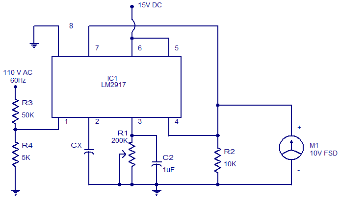
The circuit diagram of a simple capacitance meter using IC LM2917 is illustrated. The LM2917 is a high-gain monolithic frequency-to-voltage converter IC from National Semiconductors. While the primary application of the LM2917 is in tachometers, it can also be...
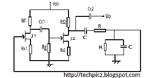
The Wien bridge oscillator utilizes a balanced Wien bridge as its feedback network. Two-stage common source amplifiers provide a 360-degree phase shift to the signal. The attenuation of the bridge is calculated to be 1/3 at the resonant frequency....
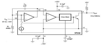
The circuit diagram of a voltage-to-frequency (V/F) converter is presented, designed to handle negative input voltage. It employs the VFC32 voltage-to-frequency converter, which is commonly utilized in various applications. The V/F converter circuit is essential in converting an analog voltage...
This circuit is a dual voltage regulated power supply, +12, -12, 0 volt. It uses the 7812 and 7912 regulators. You need a 18VCT, 1A transformer at input. More: Caution: Input / Ground are reversed between the 7812 and...
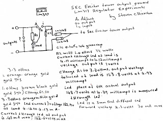
The following experiment demonstrates how Mr. Steven successfully extracted free energy from air using his home-built secondary exciter coil tower. He utilized this energy to power a small LM317 power supply unit. During the process, he hand-wound his coils...
The LM317T is an adjustable three-terminal positive voltage regulator that can supply over 1.5 amps with an output voltage range of 1.25 to 37 volts. It features built-in current limiting and thermal shutdown, making it highly reliable and resistant...