
Full-featured Dual H-bridge

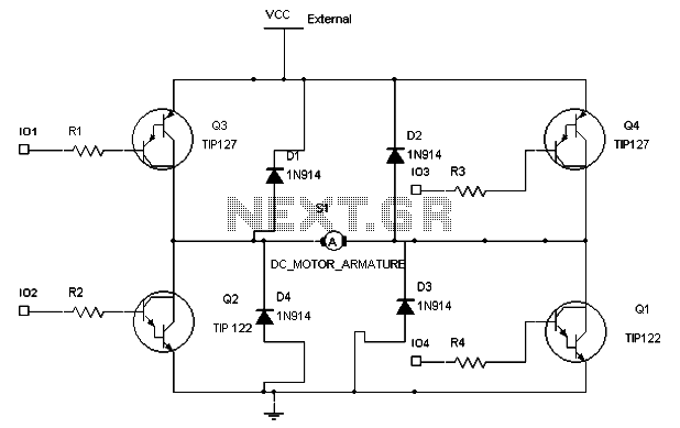
The 6-transistor H-bridge is a versatile circuit configuration used for controlling the direction and speed of DC motors. This design utilizes six bipolar junction transistors (BJTs) arranged in a bridge configuration, allowing for bidirectional control of the motor. The transistors are typically paired in two sets, with each set responsible for controlling one direction of motor rotation.
In operation, the H-bridge can be activated in one of two ways: by applying a positive voltage to one pair of transistors while turning off the opposite pair, or vice versa. This switching mechanism enables the motor to rotate in either direction. The inclusion of additional components, such as diodes, can provide protection against back EMF generated by the motor, enhancing circuit reliability.
The circuit can be further modified to include pulse-width modulation (PWM) for speed control, allowing for finer adjustments in motor speed by varying the duty cycle of the control signals. This approach not only improves energy efficiency but also reduces heat generation in the transistors.
In summary, the 6-transistor H-bridge designed by Mark Tilden is an effective solution for motor control applications, offering flexibility in operation and the potential for further enhancements through additional circuit modifications. The variations discussed in Mark's article highlight the adaptability of the design to meet different application requirements.This is a slightly revised version of the 6-transistor H-bridge designed by Mark Tilden and found on the BEAM Tek website (now only available via archive). I encourage anyone interested in H-bridges to read Mark's article, as it gives an excellent step-by-step explanation of how the bridge works.
In particular, it discusses variations on the bridge, such as the positive-input and negative-input versions. 🔗 External reference
Related Circuits
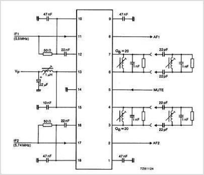
The TDA3567 is a monolithic integrated decoder designed for the NTSC color television standards. It incorporates all the necessary functions for the demodulation of NTSC signals. Additionally, it features a luminance amplifier and an RGB matrix amplifier. These amplifiers...
Can simulate the character Mu symbol. A bone dish SET code is needed that effectively manages the decimal point. An inverted J is required to open its mouth. Left foot circuit diagram. The project involves designing a circuit that simulates...
As readers may know, there are several power amplifier projects, including two that utilize integrated circuit (IC) power amplifiers, commonly referred to as power op-amps. Both of these projects have gained popularity, and this new project is not intended...
To maintain a constant speed of the motor under varying load conditions, a control application circuit is required. An H-Bridge circuit can be utilized to manage both the speed and direction of the motor. The accompanying diagram illustrates the...
Develop a cost-effective high-current circuit that utilizes PWM. The design includes flyback diodes to protect the MOSFET from the back EMF generated by the motor when the power is switched on and off via the PWM signal. This configuration...
%2Bdecoder%2BCircuit%2Bschematic%2Busing%2BM8870.png)
This DTMF (Dual Tone Multi Frequency) decoder circuit identifies the dial tone from the telephone line and decodes the key pressed on the remote telephone. For the detection of DTMF signaling, the IC MT8870DE, a touch tone decoder IC,...