
Fully Adjustable Power Supply

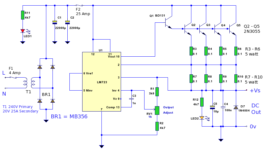
This circuit design effectively combines the functionality of an adjustable voltage regulator with current limiting capabilities, making it suitable for applications requiring precise voltage control and protection against overcurrent conditions. The LM317 serves as the primary voltage regulation component, while the MJ2955 transistor provides the necessary current amplification to exceed typical output limits. The use of a potentiometer for voltage adjustment allows for user-friendly customization of the output voltage, while the current sensing resistors ensure that the circuit can respond dynamically to load changes.
The inclusion of an op-amp comparator for current limiting enhances the reliability of the circuit, protecting both the regulator and the load from excessive current conditions. The design choice of employing a -5V reference voltage allows for a wider range of output voltage adjustment, which is particularly beneficial in applications where lower voltage levels are required. The LED indicator serves as a visual cue for the user, signaling when the circuit is operating in a current limiting mode.
Proper thermal management is critical in this design, necessitating the mounting of the LM317 and MJ2955 on a shared heatsink. This ensures that both components can effectively dissipate heat, maintaining operational stability and preventing thermal shutdown. Overall, this circuit provides a robust solution for adjustable power supply applications, balancing performance with safety features.Based on a National Semiconductor application note, this circuit uses an LM317 3-terminal regulator (REG1), chosen because of its built-in over-current and over-temperature protection. Its output is boosted up to just over 5A by the MJ2955 transistor (Q1). The output voltage is varied by adjusting the voltage on REG1`s ADJ terminal using VR1 (a 10 kO potentiometer), via the 270O resistor. Adjustable current limiting is provided by op amp IC1, used as a comparator, which monitors the voltage across the 0. 1O current sensing resistors. Once this voltage exceeds a level set by potentiometer VR2, then its output goes low, dragging down the adjust pin of REG1 and thus the output voltage.
LED1 illuminates when current limiting is occurring. The 10kO voltage adjust potentiometer (VR1) has one side connected to -5V instead of 0V so that the output voltage can be varied down to 0V instead of 1. 2V (normal limit of an LM317). Trimpot VR3 is adjusted to set the minimum output voltage to +100mV or so. Note that because the -5V rail is used as a reference, it should be regulated using an LM7905 or similar.
The LM317 3-terminal regulator and Q1 should be mounted on the same heatsink to take advantage of REG1`s thermal control. 🔗 External reference
Related Circuits
This chapter presents a variety of circuits for basic power supplies, including both line-powered and inverter types, some of which feature regulators, modulation inputs, and additional functionalities. Several circuits have been reverse-engineered from actual commercial products, and others, designed...
A 12 Volt high current 20 Amp power supply. The output voltage is variable from 12.2 Volt to 14.4V, allowing it to be set for any device requiring voltage and current within that range. This power supply unit (PSU)...
This circuit is essentially a crystal radio equipped with an audio amplifier that demonstrates considerable sensitivity, successfully receiving multiple strong stations in the Los Angeles area using a minimal 15-foot antenna. Employing a longer antenna can enhance signal strength;...
Power supply for a 25W power amplifier based on a MOSFET design. This power supply circuit is paired with a high-power audio amplifier rated at 1500 watts. The design of the power supply for the amplifier requires careful consideration....
The following circuit illustrates the connection of the Devantech SRF04 Ultrasonic Sensor to the SV203 powered PPRK Circuit Diagram. This circuit is based on the Devantech SRF04 sensor and features a minimum initiation time of 10 milliseconds for the...
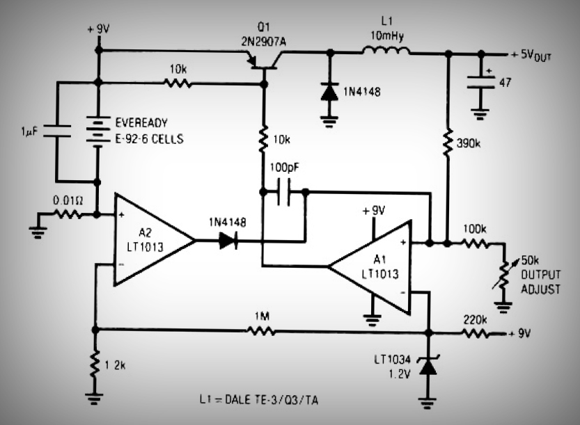
This circuit is a simple battery-powered switching regulator that provides a 5V output from a 9V source with 80% efficiency and a 50 mA output capability. When Q1 is on, its collector voltage increases, causing current to flow through...