
High Speed Photography Strobe Light

The design of the homemade strobe flash unit emphasizes the need for a compact, efficient, and high-speed light source for capturing fast-moving subjects. The use of a U-shaped xenon flash lamp allows for a significant reduction in pulse duration, making it suitable for high-speed photography. The integration of a pulse transformer not only boosts the voltage necessary to ionize the lamp but also ensures that the energy delivery is rapid and efficient. The choice of components, including the capacitors and the SCR, reflects a careful consideration of the circuit's performance under high voltage conditions.
The pulse-forming circuit, which includes a single transistor amplifier, plays a critical role in ensuring that the SCR is triggered effectively, producing a sharp and precise pulse that activates the flash lamp. The implementation of a momentary contact switch for testing purposes allows for easy verification of the circuit's functionality without the need for continuous operation.
Overall, this schematic represents a practical approach to building a high-speed light source, demonstrating how readily available components can be utilized to create an effective solution for capturing fleeting moments in photography. The resulting light curve, with its significantly reduced pulse length, illustrates the effectiveness of the design in achieving the desired performance.In order to take a high speed photograph one must either have a very fast shutter or light source. We followed the latter course and first examined an commercial flash unit to determine its light profile. This was accomplished by exposing a phototransistor connected in an emitter follower configuration with a relatively low impedance emitter resistor to the flash and viewing the resistor voltage
with an oscilloscope. Since we did not have a fast digitizer or camera available the observed trace was roughly hand sketched. The figure to the left shows the observed data. The phototransistor circuit appears in the right of the figure and the light curve of the commercial flash unit is shown at the lower left.
It can be seen that the pulse length is around 175 µs which is far too long. For example, a 130 m s-1 object (295 mph) will travel 22 mm in that time. We set about to build our own light with a significantly shorter pulse length. Fortunately, a U-shaped xenon flash lamp and companion pulse transformer were available from a local Radio Shack (and still are although the pulse transformer is now a special order item) and there were a few high voltage capacitors in the junk box. A high voltage (several hundred volt) power supply was also laying about which was built for another project at least twenty years ago.
A very nice reflector was obtained from a hand-held lantern, drilled out to pass the flash lamp, and attached to a small plastic box with epoxy. The electrical components were mounted free-standing inside the box, a male DB-9 connector was used to connect to the high voltage source, a "short-to-fire" connector was implemented with a female 1/8" phone jack, and a momentary contact switch was utilized as a "push-to-test" button.
The following figure shows a collection of views of the home-made strobe flash unit. The resulting light curve for this home-made unit is also shown in the figure at the top of this page. The pulse length is approximately 30 µs, about one-sixth of the commercial unit. The relative areas of the two curves can be compared to determine the change in relative exposure. The home-made unit emits about one-fifth of the total light of the commercial unit. The electrical schematic of the strobe light is shown in the figure below. The high voltage (400 VDC, maximum) is applied directly to the main capacitor (4 µF, 450 V) which is directly connected to the main terminals of the flash lamp.
The connections between the capacitor and lamp are relatively heavy, low inductance straps to minimize their effect on the flash`s pulse length. The pulse transformer is set in a step-up configuration and its high voltage secondary is connected to the ionization electrode of the lamp.
The low(er) voltage primary is connected to a smaller capacitor (0. 02 µF, 300 V) through a very high impedance voltage divider. In operation, this capacitor charges to one-half the main voltage through the divider and is discharged through the transformer`s primary by momentarily shorting the divider to ground by a silicon-controlled rectifier (SCR, 400 PIV, 4 A) The rest of the circuit is a single transistor amplifier and pulse-forming circuit which generates a sharp pulse with sufficient current to trigger the SCR`s gate. It will be activated either by depressing the "push-to-test" switch or by shorting out the contacts of the jack.
🔗 External reference
Related Circuits
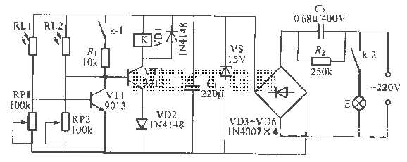
This is a remote-controlled light switch circuit that can be used for remote control toys, flashlight operation, or laser pointers. When the light from a torch illuminates the photosensitive resistor RL2, its resistance decreases, causing transistor VT2 to turn...
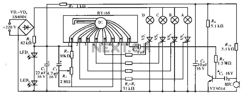
The circuit operates with a controller that includes a power supply circuit, a control circuit, and an audio amplifier, which are three distinct components. The power circuit comprises diodes VD1 to VD4, resistor R1, capacitor C1, LED1, LED2, and...
There are numerous used batteries available, primarily AA size, from various electronic devices such as remote controls and cameras. Disposing of these batteries often raises concerns due to their residual charge. While rechargeable batteries are an alternative, they may...
A combined monostable multivibrator using the 555 timer integrated circuit, along with a pair of light control comparators. This circuit can be utilized to control a load based on the timing parameters set within the circuit. The circuit comprises a...

This is a simple automatic light switch circuit designed for bedrooms. After construction, connect the input terminals of this circuit in parallel to the existing light fixture. The automatic light switch circuit operates using a photoresistor (LDR) and a transistor...
As is commonly the case, this supply was born of necessity. There is absolutely nothing special about the circuit, except that as shown, it is quite capable of up to 20 Amps intermittently or 10A continuous. Simply use a...