
Function Generator
IC2 is an LF351 operational amplifier configured as a direct-coupled non-inverting buffer, providing isolation between the waveform generator and enhancing output current. An output attenuator is formed by 2.2k and 47-ohm resistors. The high output can achieve a maximum amplitude of approximately 8V peak-to-peak for the square wave, around 6V for the triangle wave, and about 4V for the sine wave. The low amplitude controls allow for testing amplifiers, with achievable amplitudes of 20mV and 50mV. Proper adjustment of the two 100k preset resistors can reduce sine wave distortion to less than 1%. While monitoring the output waveform ideally requires an oscilloscope, an alternative is the Winscope software, which utilizes a computer's sound card to function as an oscilloscope, albeit with a frequency limit of around 20kHz. Winscope is available as freeware and includes features such as storage capabilities and a spectrum analyzer.
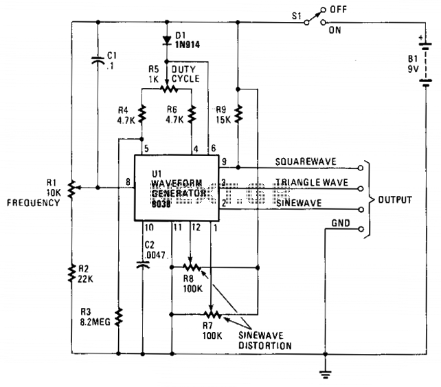
To connect the circuit to Winscope, a lead should be created to connect the sound card's stereo line input to the high output of the function generator. The output level should be set to high, the waveform shape to sine, and the frequency range to 1k to 10k (using a 22nF capacitor). The displayed waveform on Winscope should represent an undistorted sine wave. The waveform may flicker due to the sampling nature of the sound card, but using the "hold" button will stabilize the display. Adjustments to the preset resistors should be made to ensure the sine wave peaks are rounded and well-defined. The interaction between the two presets means that adjustments to one will affect the other, requiring careful calibration. After achieving a satisfactory sine wave appearance, the FFT button on Winscope can be pressed to perform a fast Fourier transform, displaying a spectrogram of the input. A pure sine wave will show a single spike in the spectrogram, indicating the fundamental frequency without harmonics, while a distorted sine wave will exhibit additional spikes due to odd and even harmonics. Once the sine wave is aligned correctly, the other waveform shapes will also be set up appropriately.Built around a single 8038 waveform generator IC, this circuit produces sine, square or triangle waves from 20Hz to 200kHz in four switched ranges. There are both high and low level outputs which may be adjusted with the level control. This project makes a useful addition to any hobbyists workbench as well. Allof the waveform generation is produce d by IC1. This versatile IC even has a sweep input, but is not used in this circuit. The IC contains an internal square wave oscillator, the frequency of which is controlled by timing capacitors C1 - C4 and the 10k potentiometer. The tolerance of the capacitors should be 10% or better for stability. The square wave is differentiated to produce a triangular wave, which in turn is shaped to produce a sine wave.
All this is done internally, with a minimum of external components. The purity of the sine wave is adjusted by the two 100k preset resistors. The wave shape switch is a single pole 3 way rotary switch, the wiper arm selects the wave shape and is connected to a 10k potentiometer which controls the amplitude of all waveforms. IC2 is an LF351 op-amp wired as a standard direct coupled non-inverting buffer, providing isolation between the waveform generator, and also increasing output current.
The 2. 2k and 47 ohm resistors form the output attenuator. At the high output, the maximum amplitude is about 8V pk-pk with the square wave. The maximum for the triangle and sine waves is around 6V and 4V respectively. The low amplitude controls is useful for testing amplifiers, as amplitudes of 20mV and 50mV are easily achievable. The two 100k preset resistors adjust the purity of the sine wave. If adjusted correctly, then the distortion amounts to less than 1%. The output waveform ideally needs to be monitored with an oscilloscope, but most people reading this will not have access to one.
There is however, an easy alternative:- Winscope. This piece of software uses your soundcard and turns your computer into an oscilloscope. It even has storage facility and a spectrum analyser, however it will only work up to around 20KHz or so. Needless to say, this is more than adequate for this circuit, as alignment on any range automatically aligns other ranges as well.
Winscope is available at my download page click here. Winscope is freeware and designed by Konstantin Zeldovich. After downloading, read the manual supplied with winscope and make up a lead to your soundcard. My soundcard is a soundblaster with a stereo line input, i made up a lead with both left and right inputs connected together. Connect the lead to the high output of the function genereator, set the output level to high, shape to sine, and use the 1k to 10k range, (22nF capacitor).
A waveform should be displayed, see the Figure 1 below:- Here an undistorted sine wave is being displayed. The display on winscope may flicker, this is normal as it uses your soundcard to take samples of the input waveform.
The "hold" button on winscope will display a steady waveform. Adjust the preset so that the top of the sine wave has a nicely rounded peak. Then adjust the other preset, again an incorrectly adjusted waveformis shown below: The two presets work together, so adjusting one affects the other. A little is all that`s needed. When your waveform is adjusted and looks similar to Figure 1 press the FFT button on winscope. This will preform a fast fourier transform and the displayed output will be a spectrogram of the input.
For a pure sine wave, only one signal is present, the fundamental frequency, no harmonics will be present and so a spectrogram for a pure sine should contain a single spike, see Figure 2 below:- A distorted sine wave will contain odd and even harmonics, and although the shape of the sine may look good, the spectrogram will reveal spikes at the hormonics, see below:- Once alignment of the sine wave is complete, the other wave shapes will also be set up correctly. Bel 🔗 External reference
Related Circuits
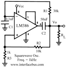
Several operational amplifier circuits are presented here, configured as square wave oscillators. A square wave is a periodic pulse train with a 50 percent duty cycle. The operational amplifier functions as a high-gain amplifier, and oscillation is achieved with...
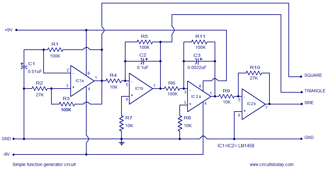
A simple function generator circuit utilizing the LM1458 is presented here. The LM1458 is a dual general-purpose operational amplifier. The two op-amps within the LM1458 share a common bias network and power supply line, yet operate independently. The function generator...
PWM waveforms are frequently employed to regulate the speed of DC motors. The mark/space ratio of the digital waveform can be established either by utilizing an adjustable analog voltage level (as seen in a NE555-based PWM generator) or through...
This project presents a useful device for the beach, intended to deter individuals from touching personal belongings left on a towel while swimming. It can also be employed in an office or workshop setting. The circuit, compact in size...
The circuit is designed around the Intersil 8038CC. The frequency range is approximately 20 Hz to 20 kHz, providing a tuning range of 1000:1 with a single control. The output frequency is determined by the value of capacitor C2...
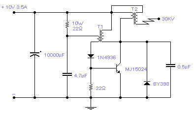
Easy to build, this high voltage generator is capable of generating up to 50KV but the breakdown voltage of the coil limits the voltage to a value somewhat lower. T2 is the ignition coil of a car and also...