
Using the MCU Timers

The timer subsystem in microcontrollers serves multiple functions, including event counting, time delay generation, and pulse width modulation (PWM) signal generation. The TCNT counter operates in conjunction with various control registers that configure its mode of operation, such as normal mode, CTC (Clear Timer on Compare Match) mode, or PWM mode.
In normal mode, the TCNT increments on each clock cycle until it reaches its maximum value, at which point it resets to zero. In CTC mode, the timer counts up to a predefined value stored in a compare register (OCR), at which point an interrupt can be triggered, or an output pin can be toggled. PWM mode allows the generation of varying duty cycles for output signals, which is essential in applications such as motor control and signal modulation.
The programmable prescaler plays a crucial role in determining the timer's resolution and maximum count duration. By dividing the system clock frequency, the prescaler allows for longer time intervals to be measured with the same counter width. The selection of the prescaler value is often done via specific bits in a control register, allowing for flexibility in timing applications.
External clock sources can also be utilized, providing additional versatility in timer operations. This is particularly useful in applications requiring synchronization with external events or signals.
Overall, the timer subsystem's architecture is designed to be highly configurable, allowing for a wide range of applications in embedded systems, from simple timing tasks to complex signal generation and event handling. Understanding the operational principles and configurations of the timer subsystem is essential for effectively utilizing microcontrollers in various projects.Although there are significant variations between different implementations of the general-purpose timer in different microcontrollers, there are many similarities in the principles of operation and the structure of the timer subsystem. The central element of the timer subsystem is a counter, TCNT (8 or 16-bits in length), which may be read or (so
metimes) written by software. The clock for TCNT is obtained either from the system clock, divided by a programmable prescaler, or an external clock applied to one of the MCU pins. The software control upon the timer is performed by means of the. 🔗 External reference
Related Circuits
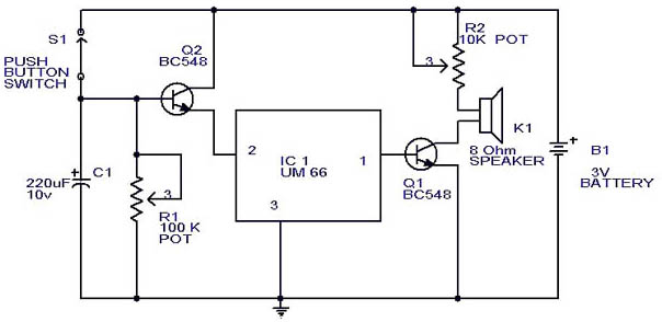
This circuit is a slight modification of a previous design. In the earlier version, the switch needed to be held down for the entire duration of the music playback. In this updated circuit, pressing the push button once charges...
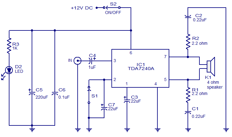
The audio amplifier presented here is based on the TDA7240 integrated circuit from ST Microelectronics. The TDA7240 is capable of delivering 20 watts of audio output power into a 4-ohm load. It requires a minimal number of external components...

The circuit is designed to regulate a dual power supply that provides +12V and -12V from the AC mains. Such a power supply is an essential tool for an electronic hobbyist's workbench. The schematic of the circuit includes components...
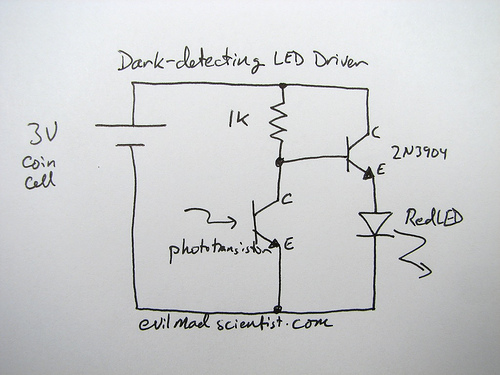
A circuit that uses a phototransistor to create a light-sensitive switch. When there is no light in the room, the LED connected to the phototransistor lights up, and when there is light, the LED turns off. Any schematic or...
The following circuit illustrates a 2000W Power Amplifier Circuit Diagram. This circuit utilizes the BC560C transistor. Features include a robust design. The 2000W power amplifier circuit is designed to deliver high output power suitable for various applications, including audio amplification...
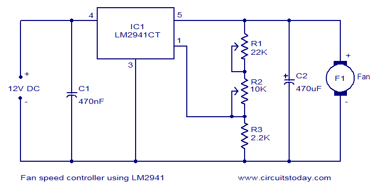
Numerous electronic circuits designed for fan speed control have been documented, and this one presents an alternative method. The circuit diagram illustrates a 12V DC fan speed controller utilizing the LM2941CT integrated circuit, which is a low dropout 1A...