
Fuse-Cum-Power Failure Indicator with alarm

The Fuse Cum Power Failure Indicator is an essential device designed to alert users of power interruptions, thereby preventing potential damage to connected electronic equipment. The core of this circuit is the NE555 timer IC, which operates in a monostable mode to provide a time delay for the indication signal.
The circuit begins with a thermistor, a temperature-sensitive resistor that changes its resistance based on ambient temperature. In this application, it is used to detect the absence of power. When the power supply is interrupted, the thermistor's resistance changes, triggering the NE555 timer.
The NE555 timer is configured with a resistor-capacitor (RC) time constant that determines the duration of the output signal. When the power failure is detected, the timer activates, generating a high output signal for a predetermined period. This output can be used to drive an LED indicator, providing a visual alert to users.
The complete circuit includes additional components such as resistors, capacitors, and possibly a relay, depending on the load requirements. The parts list should detail each component's specifications, including resistance values, capacitance, and power ratings, ensuring that the circuit operates reliably under various conditions.
Overall, the Fuse Cum Power Failure Indicator is a practical solution for monitoring power supply status, safeguarding electronic devices from unexpected outages.Fuse Cum Power Failure Indicator employs thermister and timer IC NE555 circuit diagram with parts list of fuse cum power failure indicator indicate power failure. 🔗 External reference
Related Circuits
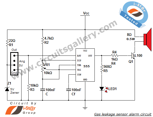
This article discusses a home security alarm circuit designed to detect LPG gas leakage. The circuit utilizes a gas sensor module, SEN 1327, which incorporates a QM 6 gas sensor. The output signal from this gas sensor module is...
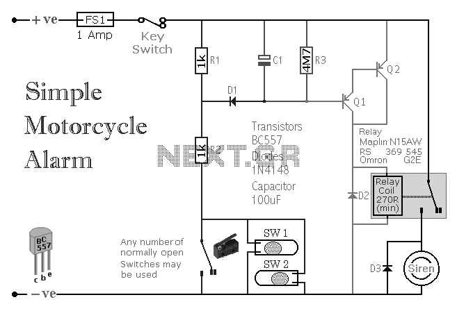
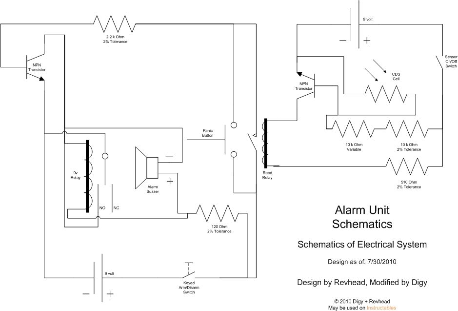
A simple transistor-based motorcycle alarm circuit. This circuit is easy to build and designed to operate at 12 volts. However, by replacing the relay with one that has a 6-volt coil, it can also provide protection at that voltage. The...
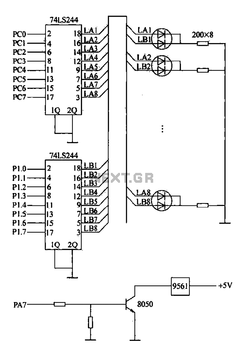
Alarm interface circuitry featuring a two-color light-emitting diode (LED) display. When LAi is at a high level and LBi is low, the green LED lights up; conversely, if LAi is low and LBi is high, the red LED lights...
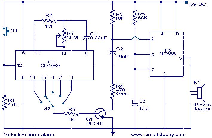
The following circuit illustrates a Selective Timer Alarm Circuit based on the 4060 Integrated Circuit (IC). Features include an automatic turn-off mechanism for the alarm after a specified duration. The Selective Timer Alarm Circuit utilizes the 4060 IC, which serves...
Learn how to strengthen your security system, regardless of its size, with this innovative and customizable laser grid. Once an individual crosses the threshold, the system activates... The concept of a customizable laser grid for security applications involves the deployment...
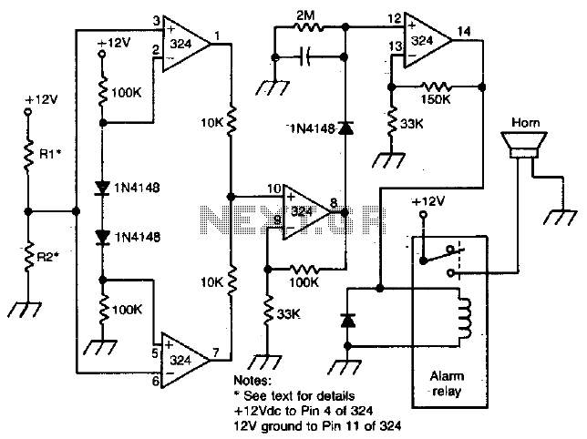
Removing R1 or R2 from the circuit allows a potential thief to break a hidden wire that connects R1 to +12 V and R2 to ground. This action activates the alarm for approximately five minutes. The circuit in question is...