
Selective Timer Alarm Circuit With 4060IC

The Selective Timer Alarm Circuit utilizes the 4060 IC, which serves as a versatile timer and oscillator. This IC is particularly advantageous due to its ability to generate a precise time delay, making it suitable for applications requiring timed events. The circuit typically consists of resistors and capacitors that determine the timing interval, which can be adjusted to meet specific requirements.
The operation of the circuit begins when the timer is activated, initiating the oscillation within the 4060 IC. The output of the IC drives an alarm system, such as a buzzer or LED indicator, that signals the user when the timer is active. After the designated time elapses, the 4060 IC automatically disables the output, thereby turning off the alarm. This feature is particularly useful in scenarios where an alert is needed for a limited duration, ensuring that the alarm does not continue indefinitely.
The design of the circuit can be modified to include additional functionalities, such as manual reset options or adjustable timing settings. By varying the resistor and capacitor values, the timing range can be tailored to suit different applications, from simple reminder alarms to more complex timing functions in automated systems. Overall, the Selective Timer Alarm Circuit based on the 4060 IC provides a reliable and efficient solution for timed alert mechanisms in various electronic projects.The following circuit shows about Selective Timer Alarm Circuit. This circuit based on the 4060IC. Features: The alarm will automatically turn OFF after the .. 🔗 External reference
Related Circuits
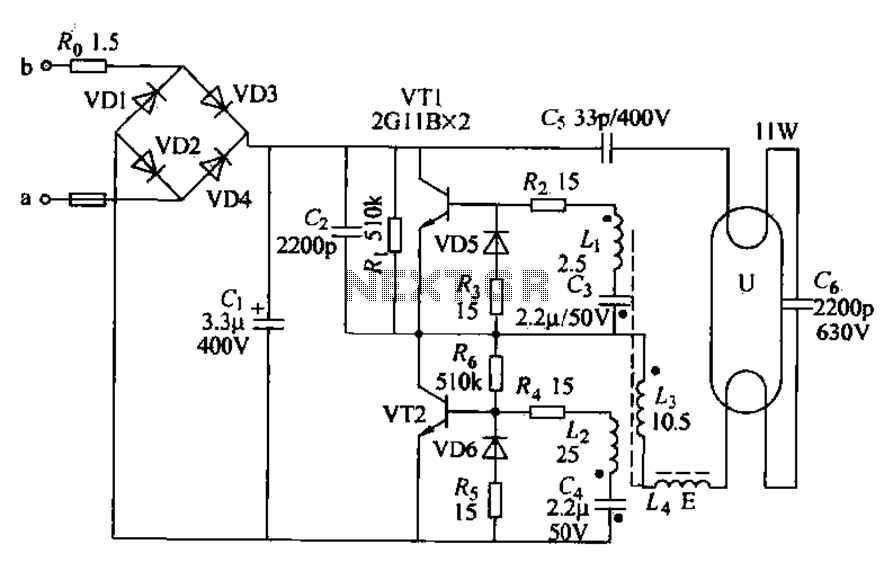
Energy-saving lamps are categorized into self-ballasted compact types and single-ended structures. They can also be classified based on appearance into various forms such as double-tube, four-tube, six-tube types, and others. The lifespan of energy-saving lamps is approximately ten times...
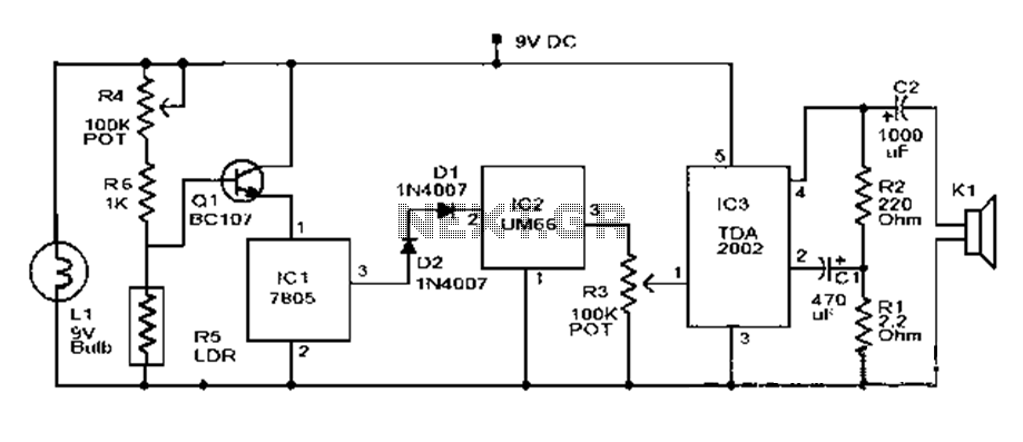
This document outlines a basic fire alarm circuit utilizing an LDR (Light Dependent Resistor) for fire detection. The circuit is designed to generate an audible alarm in response to smoke, which affects the LDR's resistance. In the absence of...
Presented circuit is very simple. With more sampling, I refrained from using the converter and lamp designed for powering three NiCd or NiMH batteries. Because the voltage difference between the battery and the LED is very small, this arrangement...
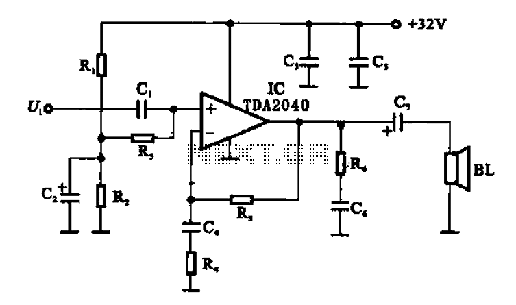
An integrated power amplifier TDA2040 is used in an OTL (Output Transformer-Less) power amplifier circuit, which operates with a +3V single supply as the working voltage. This circuit has a voltage gain of 30 dB (approximately 32 times magnification),...
Advanced power control systems utilize electronic components such as thyristors for power switching, motor control, and other applications. These systems are involved in inverter design, lamp dimming, and speed control of motors. Triacs are the most commonly used semiconductor...
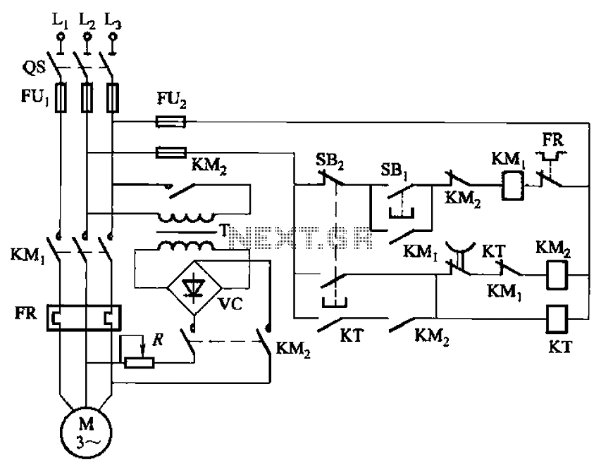
The circuit depicted in Figure 3-135 employs a time relay (KT) to determine the braking time. The circuit utilizes a time relay, which is a crucial component for controlling the duration of the braking process. The time relay KT is...