
GaAsFET amplifier circuit

The circuit described is a sophisticated control mechanism that utilizes an LM123 voltage regulator to maintain stable output voltage levels while interfacing with a DC-DC converter. The integration of the LM123 allows for efficient voltage regulation, ensuring that the power supply remains consistent even under varying load conditions. The choice of a GaAsFET power relay enhances the performance of the power amplifier, providing high efficiency and fast switching capabilities.
The N-channel MOSFET serves as a critical component in the control circuit, enabling precise control over the base of the 2N6107 pass transistor. By pulling the base to an appropriate level, the MOSFET ensures that the transistor operates in the saturation region, allowing for maximum current flow and minimal heat dissipation. This configuration is essential for maintaining the reliability and longevity of the circuit.
Moreover, the circuit's ability to supply Tum leak during negative potential failures on the gate indicates a protective feature that enhances operational safety. This characteristic ensures that the circuit can handle unexpected conditions without compromising overall functionality.
In summary, this control circuit exemplifies a well-designed integration of components that work together to provide efficient power management and reliable operation in electronic applications, particularly in power amplification scenarios.The control circuit operates to double from a positive supply, which, when turned on the power of the first door. and goes off when the first drain as shown in FIG. This circuit integrates the LM123, a three-terminal positive regulator and a dc dc + converter, whose output power drains and gates of GaAsFET-power relay in a power amplifier.
The controller output drives a three-terminal DC + DC converter - which exit through an N-channel lFET properly so as to pull the base of the series pass transistor 2N6107 at a level to turn it on. The circuit will supply Tum leak every time the negative potential on the gate fails.
Related Circuits
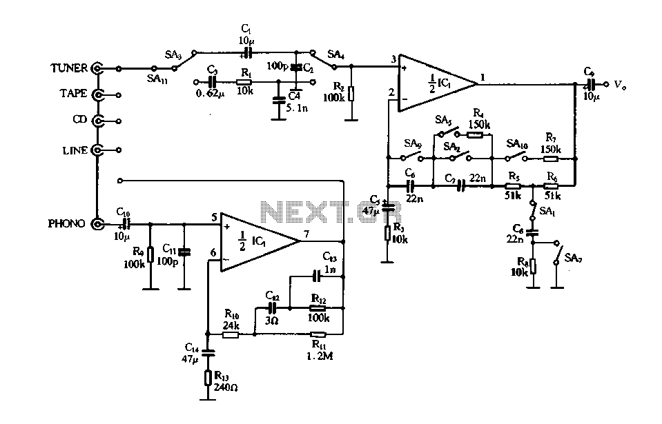
Figure 4-12 illustrates a five-speed tone selector schematic, which includes circuit components such as IC1, an electromagnetic phono equalizer amplifier, and external RC components. The schematic also features a selection switch for the tone control circuit. When the straight...
The following circuit illustrates the use of the AD8531 integrated circuit for the automatic control of LCD panel backlighting. Features include the ability to compensate for aging effects. The AD8531 is a precision operational amplifier that is well-suited for applications...
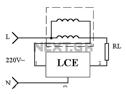
This is an application circuit of the device as illustrated in principle. In the meter, the voltage and current coils are connected to the power line, regardless of whether a load is connected. The voltage coil consistently draws power,...
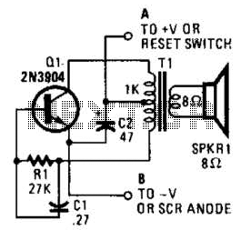
This is a simple low-level noise maker that is ideally suited for certain alarm applications. When the sounder is located in another part of the building, the sound level is loud enough to be heard but is not loud...
The Tiny Audio Amplifier kit is a good choice for battery operation. It is based on LM386 IC. Power supply - 6 - 12 VDC. Output power - 1 W, 8 Ohm. The quiescent power drain is only 24...
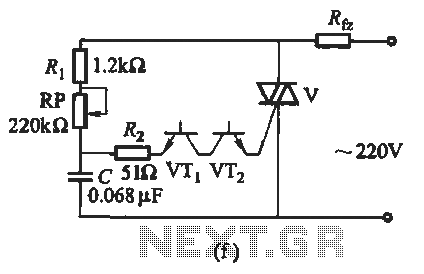
The introduction for a unidirectional thyristor trigger circuit is also applicable to the TRIAC. Various configurations are presented in Figure 16-28. Figures 16-28 (a) and (b) illustrate a direct trigger circuit; Figure 16-28 (c) depicts a dual diode trigger...