
Game feeder controller

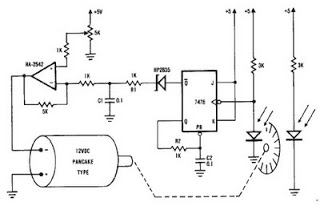
Diode D1 serves as a blocking diode, ensuring that capacitor C1 discharges through R10 and R13. The window comparator monitors voltages that fall between one-third and two-thirds of the supply voltage. When the voltage is within this range, the output of the window comparator (pins 13/14) goes high. This activation turns on transistors Q1 and Q2, which energize relay K1. The energized relay creates a DC path to ground, activating motor M1, which reloads the feeder. Additionally, the timer circuit provides protection against triggering due to lightning. The on-time duration of relay K1 is determined by the charge cycle of C1 with R11 and R9, or the discharge cycle of C1 with R10 and R13. Adjusting the value of either a resistor or the capacitor alters the timing cycle.
The LM339 quad comparator is a versatile device that can accommodate multiple functions within a single circuit, enhancing its efficiency and reducing component count. The Schmitt trigger configuration, utilizing LDR1 and the associated resistors, provides hysteresis, allowing for stable switching behavior in the presence of noisy signals. This is particularly advantageous in environments where fluctuations may occur, ensuring reliable operation.
The timer circuit's design is crucial for controlling the duration of the relay's activation and, consequently, the operation of motor M1. The selection of resistors R9, R10, R11, and R13, along with capacitor C1, defines the time constant of the circuit, which dictates how quickly the relay engages and disengages. The incorporation of a voltage divider with resistors R1, R2, and R3 allows for precise voltage reference levels for the window comparator, ensuring that the system reacts appropriately to varying input conditions.
The use of diode D1 to block reverse current flow protects the circuit components from potential damage during the discharge process of capacitor C1. This design consideration is essential for maintaining the integrity and longevity of the circuit.
Overall, the described circuit effectively integrates multiple functionalities, providing a robust solution for applications requiring precise timing control and voltage monitoring, while ensuring operational stability in variable conditions.The circuit is built around an LM339 quad comparator, Ul, which forms the basis of a Schmitt trigger, timer circuit, and a window comparator. One comparator within the LM339 (pins 1, 7, 6), plus LDR1, R4, R5, R6 and R8, is used as a Schmitt trigger.
The timer circuit (which receives its input from the Schmitt trigger) consists of R9, RIO, Rll, R13. The last two-fourth's of Ul (pins 8, 9, 10, 11, 13 and 14) are wired as a window comparator. The two inputs to the window comparator are derived from the charge on capacitor Cl—which is fed to pins 9 and 10 of Ul. The other inputs are picked from two points along a voltage-divider network, consisting of Rl, R2, and R3.
DiodeD1 is used as a blocking diode, forcing capacitor Cl to discharge through RIO and R13. The window comparator looks for any voltage falling between one-third and two-thirds of the supply voltage. When the voltage falls between those two points, the output of the window comparator (pins 13/14) goes high.
Transistors Ql, and Q2 are turned on, when the pins 13/14 junction goes high, energizing the relay, Kl. The energized relay provides a dc path to ground, activating the motor, Ml, which reloads the feeder.
The timer circuit also provides immunity from triggering, duei;o lightning. The on-time of relay Kl is determined by the charge cycle of Cl, Rll, and R9 or the discharge cycle of Cl, RIO, and R13. Changing the value of either a resistor or the capacitor, changes the timing cycle.
Related Circuits
A simple encoder circuit for a DC motor can be constructed using the provided circuit diagram. The system includes the HA-2542 operational amplifier, a small 12 V DC motor, and a position encoder. During operation, the encoder generates a...
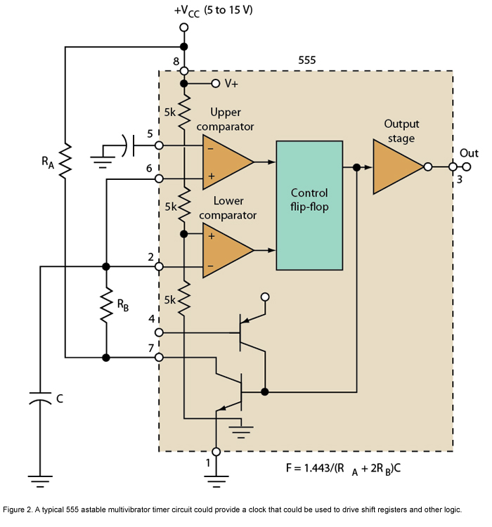
Micro or analog? These days, it is becoming increasingly challenging to make a choice. The 555 timer has long been regarded as a benchmark for flexibility. How does it perform today? The 555 timer IC, originally introduced in 1972, remains...
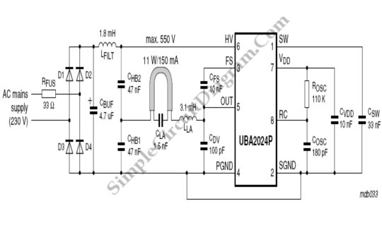
The UBA2024 is a half-bridge integrated circuit (IC) and a 550 V lamp controller. This device features 9-ohm switches that support standard compact fluorescent lamp (CFL) applications up to 15 W. The UBA2024 is specifically designed for driving compact fluorescent...
National Instruments Multisim now features microcontroller unit co-simulation capabilities, enabling the inclusion of a microcontroller, programmed in assembly or C code, within SPICE-modeled circuits. The MCU functionality in Multisim allows students, educators, and professional users to program MCUs in...
The 230 V, 50 Hz supply is stepped down using a voltage transformer, while a current transformer is utilized to extract the current waveforms. The output of the voltage transformer corresponds to the voltage across the load, and the...
Game Show Indicator Lights (Who's First) Circuit The circuit below activates a light corresponding to the first of several buttons pressed in a Who's First game. Three stages are shown, but the circuit can be extended to include additional...