
Game Show Indicator Lights (Whos First)
")
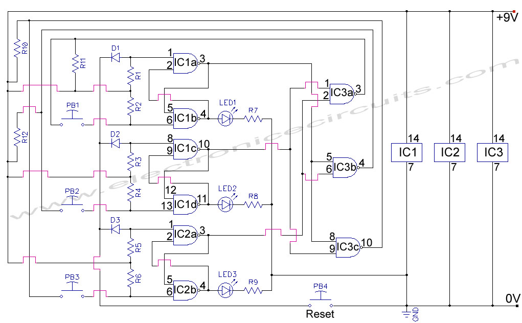
The Game Show Indicator Lights circuit is designed to determine and visually indicate which contestant presses their button first in a competitive game setting. The basic configuration consists of multiple input buttons, each connected to a logic circuit that detects the first button pressed.
In the initial stage of the circuit, each button is linked to a resistor-capacitor (RC) network that helps debounce the button press, ensuring that only a clean signal is registered when a button is activated. The outputs from the buttons are fed into a priority encoder or a simple comparator circuit that assesses the signals and determines which button was pressed first.
Once the first button is identified, the logic circuitry activates a corresponding indicator light, which can be implemented using light-emitting diodes (LEDs) or incandescent bulbs. The indicator lights are connected through a transistor switch or a relay, allowing for higher power output to drive the lights without damaging the logic components.
For scalability, the circuit can be expanded to include additional buttons and corresponding indicator lights. This is achieved by cascading additional stages of logic or using multiplexing techniques to manage multiple inputs efficiently. The design can also incorporate features such as a reset button to clear the previous indication and prepare for the next round of play.
Overall, the Game Show Indicator Lights circuit combines logic design with visual output to create an engaging and interactive experience for participants, making it suitable for various game show formats and competitive events.Game Show Indicator Lights (Who`s First) Circuit The circuit below turns on a light corresponding to the first of several buttons pressed in a Who`s First game. Three stages are shown but the circuit can be extended to include a.. 🔗 External reference
Related Circuits
This circuit allows for the measurement of the actual output power of an amplifier. It can be housed in a box to function as a measurement instrument. The circuit for measuring amplifier output power typically includes a few essential components:...
First Response Monitor, Input Selector, Game Circuit. This circuit is utilized for first response applications as it aids in monitoring various responses in games. The First Response Monitor circuit is designed to facilitate real-time monitoring and selection of input signals...
IC4, C1, R1 and R2 are used for the clock pulse which is fed to both the counters IC2 and IC3 Pin 14. IC1 is a Flip Flop and is used as a switch to enable either IC2 or...
A 1999 Chevrolet Suburban has non-functional headlights. The fuses and circuit breakers have been checked and found to be operational. According to the owner's manual, the headlamps are protected by a circuit breaker located within the lamp switch, but...

The circuit for the LED solar lantern lights is designed using a 6V/1W solar panel (photovoltaic panel) and a 4V/800mAh lead-acid battery. The schematic for the LED solar lantern circuit incorporates a solar panel that converts sunlight into electrical energy....
The game Tetris is implemented using a PIC16F84 microcontroller operating at 12MHz. Tetris is a classic Russian computer game where players fit blocks into a playfield. In this implementation, the video signal is generated through software, utilizing only two...