
Positive Trigger Timer Circuit
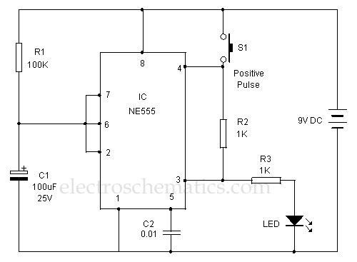
The 555 timer is a versatile integrated circuit widely used in various applications, including timing, pulse generation, and oscillator functions. In this specific design, the functionality of the reset pin is leveraged to achieve a positive output, which is an unconventional approach compared to standard configurations.
The circuit operates by connecting the reset pin (pin 4) to a control voltage that determines the timer's state. When the reset pin is held low, the timer is disabled, and the output remains low regardless of other inputs. Conversely, applying a high voltage to the reset pin allows the timer to function normally, enabling it to produce a positive output when triggered.
In typical applications, the 555 timer can be configured in monostable or astable modes. In the monostable mode, a single pulse is generated in response to an external trigger, while in astable mode, the timer oscillates between high and low states, producing a continuous square wave output. The unique design of this 555 timer allows for additional control over the output state, providing flexibility in applications where precise timing and control are critical.
The timing characteristics can be adjusted by selecting appropriate resistor and capacitor values connected to the timer. The timing interval is determined by the formula T = 1.1 * R1 * C1 for monostable mode, where R1 is the resistance and C1 is the capacitance. In astable mode, the frequency of oscillation can be calculated using the formula f = 1.44 / ((R1 + 2*R2) * C1), where R2 is another resistor in the configuration.
This innovative approach to utilizing the reset pin for output control enhances the versatility of the 555 timer, making it suitable for a broader range of applications, including signal generation, waveform shaping, and pulse-width modulation.This 555 timer is designed unusually to give a positive output through a control over its reset pin. Usually the timer IC 555 is triggered by applying a ne.. 🔗 External reference
Related Circuits
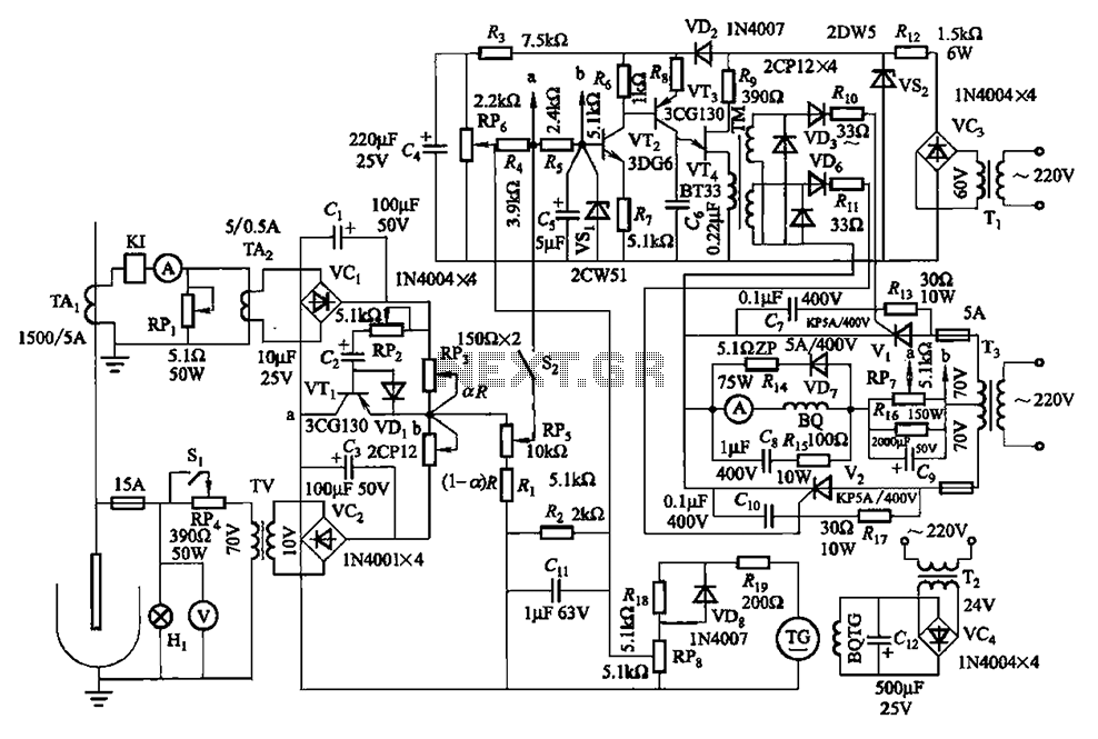
The circuit is illustrated in Figures 16-95 to 16-97. The electrode automatic adjuster demonstrates enhanced performance, featuring a high-accuracy, well-linear current output type bridge. Additionally, it incorporates a differential arc current negative feedback circuit (advanced) that allows for preemptive...
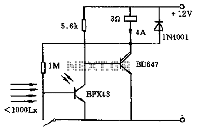
In the circuit's resting (dark) state, current flows through the electromagnet M. When light shines on the phototransistor, it turns on, causing the final stage transistor to enter the OFF state, which releases the solenoid. A 1M ohm feedback...

The proposed remote control circuit can be utilized to control any electrical device within a range of 100 meters. This concept involves modifying an existing remote bell unit circuit, making the process straightforward. However, the construction aspect necessitates electronic...
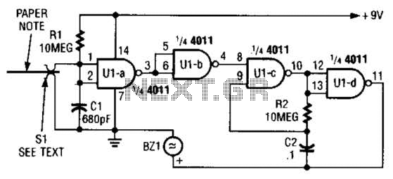
This device prevents paper notes and memos from being overlooked. A paper note placed between two fingers made of a conducting material (metal or conductive plastic) breaks the circuit, allowing pair 1 of Ul-a to go high. This causes...
The circuit operates in a parallel-fed configuration, as the DC plate current does not pass through the inductor. R3 can be substituted with an RF choke if desired. Capacitor C3 prevents B+ from appearing across the variable capacitor, which...
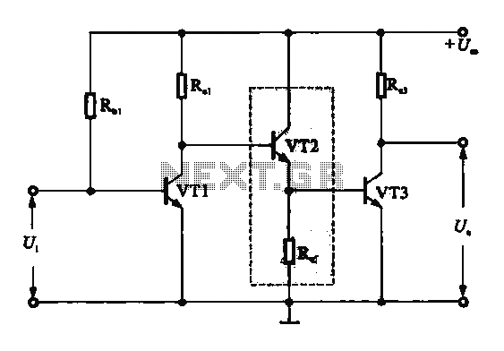
A DC-coupled multi-stage amplifier circuit consists of multiple stages of amplification using a DC-coupled configuration. Each stage utilizes NPN-type transistors, which are designed to maintain appropriate operating points at the base of each stage. As the signal progresses through...