
Gear clock using PIC 16f628A

The electronic schematic for the described clock system is centered around the PIC 16F628A microcontroller, which serves as the main controller. An external 20MHz crystal oscillator is connected to the microcontroller's oscillator pins, ensuring accurate timekeeping. The microcontroller interfaces with two push-button switches connected to digital input pins, enabling user interaction for adjusting the time.
The unipolar stepper motor, sourced from an old 5 1/4 inch floppy drive, is connected to the microcontroller through a driver circuit consisting of four transistors. These transistors act as switches to control the current flow to the motor coils, allowing for precise step control. The motor's configuration allows it to advance 1.8 degrees per pulse, with the microcontroller programmed to energize the motor coils in a sequence that corresponds to the desired rotation direction.
The gear mechanism includes a 9-tooth motor gear connected to the stepper motor, which drives a series of larger gears: a 72-tooth minute gear, an intermediate gear with a 72-tooth primary and an 18-tooth secondary, and a 72-tooth hour gear. This arrangement facilitates the correct time advancement, with the motor advancing 4 steps every 9 seconds.
The software architecture is divided into two main sections: an iterative loop for button monitoring and a timekeeping interrupt service routine. The loop continuously checks the state of the buttons, adjusting the motor's rotation accordingly. The interrupt-driven section updates an internal clock every 0.1 seconds, ensuring accurate timekeeping. Additionally, the internal clock can be monitored via a serial connection, providing real-time feedback on the clock's status.
Overall, the design emphasizes simplicity and efficiency, leveraging the capabilities of the PIC microcontroller and the mechanics of the stepper motor to create a functional and user-friendly clock system.The heart of the clock is a PIC 16f628A microcontroller (PDF). This microcontroller has an internal oscillator however an external 20MHz crystal oscillator is being used since it will have to accurately keep track of time for weeks and months. The microcontroller is interfaced to two buttons and one motor. The interface is very simple, it consists of two buttons. When the left button is pressed the clock advances time using the motor. When the right button is pressed the clock decrements time using the motor. The only issue is when you need to correct time by many hours you would have to keep the button pressed for a long time.
The stepper motor is also always energized to prevent the gears from slipping. To overcome this issue when both buttons are pressed the stepper motor is deenergized and the minute gear can be spun freely. The motor is a unipolar stepper motor that has been harvested from an old 5 1/4 inch floppy drive. This is the motor that used to move the read write heads back and forth, to get one of this size and power you’ll need to find a nice old one.
There are many sizes and styles of steppers so it may take a bit of digging to find a usable one. Modern floppy drives don’t have steppers with this level of torque. This motor moves 1.8 degrees per pulse which means that with 200 pulses it will make one full rotation. Since it’s a unipolar motor it is simple for the PIC to drive it with only 4 transistors. You will also need to be aware of motors with different number of pulses per rotation however 200 is the most common.
The gears are made out of MDF. They were painted to have a metallic look however the look I was going for was not achieved. Initially I was thinking of making the gears look like they were made of metal and left to rust for a few dozen years. I found some cool products that would give me that rusted effect but they were a bit too expensive. I settled for a can of Krylon Black Metallic Hammered Finish paint. The sample on the lid is a very nice black with subtle bit of gray. I think this might be from a bad batch since the final look is not as black as it should be. It also made taking pictures of the final clock a bit tough since even with modest lighting the glare was horrible.
The gear arrangement is as follows: 9 tooth motor gear 72 tooth minute gear with a 24 tooth secondary 72 tooth intermediate gear with a 18 tooth secondary 72 tooth hour gear To achieve the correct timing the 9 tooth motor gear is advanced 4 steps every 9 seconds. By moving 4 steps at a time the motor routines can be simple since the motor is always at rest with the same coil energized.
Code The code is basically split into two sections, there is an iterative loop that monitors the buttons for a change in state and checks if the internal clock has crossed the 9 second mark. If one of those conditions has occurred the stepper motor is driven appropriately. The other section of code is interrupt driven and it keeps track of time. An interrupt is triggered every 0.1 seconds and adjusts an internal clock as needed. There is a true running clock inside, if you connect the clock PIC pin 6 to a computer serial port operating at 9600 bps you will see the internal clock values update once per second.
The clock value in this case is arbitrary since it is never shown and will not be the same as what the gears are displaying but this same code will be used in future projects which will use this code display time. 🔗 External reference
Related Circuits
The I2C serial bus is a widely used two-wire bus for small-area networks. The I2C Clock and Data lines feature open collector (or drain) outputs for each device on the network, requiring only a single pull-up resistor. This architecture...
The following circuit illustrates a Water Level Detector Circuit Diagram. This circuit is based on the PIC12F683 microcontroller. Features include the ability of the PIC microcontroller to enter a sleep mode. The Water Level Detector Circuit utilizing the PIC12F683 microcontroller...
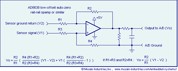
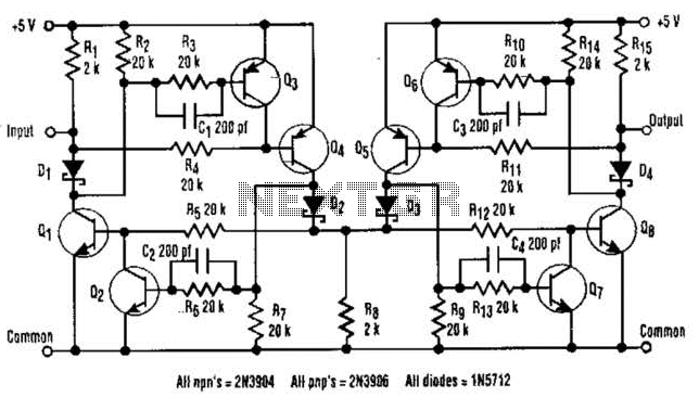
Ground loop offset errors and ground noise are eliminated by a differential amplifier or instrumentation amplifier before the analog-to-digital (A/D) conversion. The differential input amplifier addresses ground loop errors, allowing for precise measurement of non-isolated sensors. A simple operational...
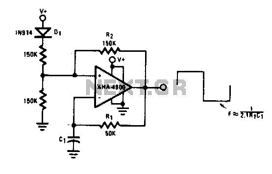
This self-starting fixed frequency oscillator circuit provides excellent frequency stability. R1 and C1 form the frequency-determining network, while R2 supplies regenerative feedback. Diode D1 improves stability by compensating for the difference between Voh and Vsupply. In applications requiring a...
This application note outlines the transmission of I²S audio data streams between two audio components using a single shielded twisted-pair (STP) wire, employing the MAX9205 10-bit LVDS serializer and the MAX9206 10-bit LVDS deserializer. Low-voltage differential signaling (LVDS) serves...
All PIC IR decoders share the same easy-to-build hardware. All components for this hardware are readily available globally. Constructing it should not take much longer than one evening. At the center of the diagram is the PIC16F84 processor, accompanied...