
General-Purpose AF Power Amplifier

The general-purpose audio frequency (AF) amplifier circuit is designed to amplify audio signals for various applications, such as audio processing, sound reinforcement, and signal conditioning. The schematic typically includes several key components: resistors, capacitors, transistors or operational amplifiers, and possibly diodes for signal clipping or protection.
The use of 1/4-W resistors indicates a focus on cost-effectiveness while maintaining adequate performance for audio applications. These resistors are suitable for handling the power levels typically encountered in audio circuits without the need for high precision components.
The circuit may consist of a multi-stage amplification configuration, where each stage contributes to the overall gain. The input stage usually employs a transistor or an operational amplifier configured as a non-inverting amplifier to provide initial gain and impedance matching. Following this, additional stages may include further amplification and tone control elements, allowing for adjustments to the frequency response of the audio signal.
Capacitors in the circuit serve various purposes, such as coupling and decoupling signals between stages, filtering out unwanted noise, and stabilizing the power supply. The choice of capacitor types, such as electrolytic or ceramic, can influence the performance characteristics of the amplifier, particularly in terms of frequency response and transient response.
Overall, this schematic serves as a fundamental design for audio amplification, suitable for hobbyist projects or educational purposes, where the emphasis is on simplicity and functionality rather than precision and high-end performance.This is a schematic diagram of general-purpose audio frequency (AF) amplifier circuit. This circuit uses cheap 1/4-W resistors, no high precision needed so.. 🔗 External reference
Related Circuits
The amplifier drives a pair of speakers using two LM3876 amplifier chip circuits (50 watts per channel) or a pair of headphones with Meier Crossfeed through a clarifier and a dual OPA2134 Opamp. It features four selectable band inputs...
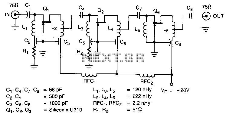
The amplifier circuit is designed for a 225 MHz center frequency, with a 1 dB bandwidth of 50 MHz, low input VSWR in a 75-ohm system, and a gain of 24 dB. Three stages of U310 FETs are utilized...
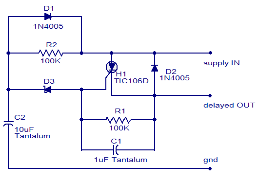
The circuit diagram presented is of a straightforward DC power delay circuit utilizing a silicon-controlled rectifier (SCR). This circuit is quite useful and can be applied in various scenarios. The operation of this circuit is uncomplicated. Upon the application...

These power supply circuits generate 500 volts, but they can be modified to supply several hundred to nearly 1000 volts by changing the zener diodes. These circuits produce high voltages and can cause dangerous shocks. Caution is advised; these...
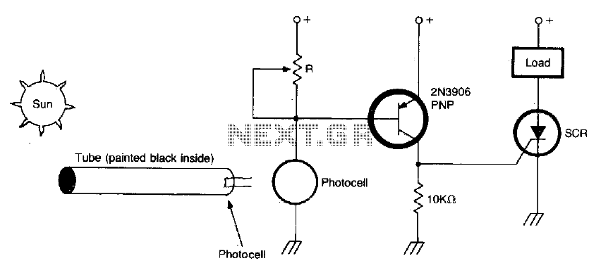
The circuit activates when light, specifically sunlight, strikes the photocell. A potentiometer, labeled R, adjusts the light level at which the alarm is triggered. Additionally, a painted tube, with a black interior, can be utilized on the photocell to...
The sound system features a de-sensitized design with a maximum range that can be increased if desired. It includes two tone controls: one offering a lift of 10 dB and the other providing a subtle cut of 3 dB....