
ghz oscillator

The low-noise block downconverter (LNB) is an essential device in satellite communication systems, primarily used to receive signals from satellites and convert them into a lower frequency range for further processing. The operation of an LNB involves several key stages, including signal amplification, frequency conversion, and filtering.
At the core of the LNB is a low-noise amplifier (LNA), which amplifies the weak signals received from the satellite dish. The LNA is designed to minimize the addition of noise to the signal, ensuring that the integrity of the received data is preserved. The amplified signal is then fed into a mixer, where it is combined with a local oscillator (LO) signal. This mixing process generates an intermediate frequency (IF) that falls within the L-Band range, typically between 950 MHz and 2150 MHz.
The choice of the local oscillator frequency is critical, as it determines the specific frequency conversion that takes place. The output from the mixer is then passed through a bandpass filter, which selectively allows the desired frequency range to pass while attenuating any unwanted signals and noise. This filtering process is vital for maintaining signal quality and ensuring that only the relevant information is transmitted to the satellite receiver.
The design of an LNB also includes components such as a dielectric resonator, which helps stabilize the local oscillator frequency, and a phase-locked loop (PLL) circuit that provides frequency control. The overall compact design of the LNB allows it to be mounted directly on the satellite dish, minimizing signal loss and improving performance.
In summary, the low-noise block downconverter plays a fundamental role in satellite communication by effectively converting high-frequency signals to a lower frequency range, thereby facilitating the transmission of data to satellite receivers. Its design incorporates advanced technologies to ensure low noise levels, high gain, and efficient frequency conversion, making it a critical component in modern satellite systems.A low-noise block downconverter (LNB) is a key element in a satellite receiver system and is responsible for converting the relatively high frequency of the received signal into the more convenient L-Band. But how do they work and what do they look like on the inside Let`s have a look! From a theoretical standpoint, a [ ] 🔗 External reference
Related Circuits
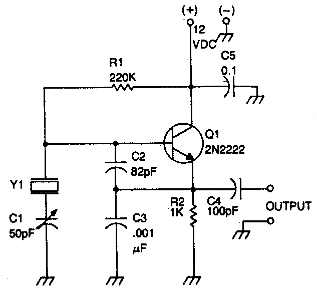
This circuit operates with fundamental-mode crystals in the frequency range of 1 MHz to 20 MHz. Feedback is regulated by the capacitor voltage divider formed by capacitors C2 and C3. The RF voltage across the emitter resistor supplies the...
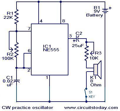
A circuit diagram for generating continuous wave (CW) Morse code is presented here. This circuit is particularly beneficial for individuals interested in practicing Ham Radio. It consists of an astable multivibrator utilizing the NE555 timer. The oscillation frequency of...
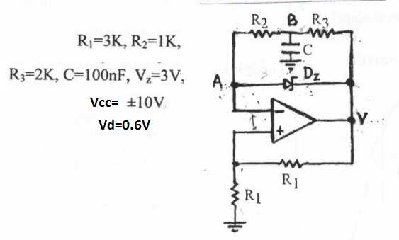
This circuit appears to be a Schmitt trigger oscillator. Based on the configuration of the resistors and capacitor, it is likely functioning as a sawtooth wave generator, with resistors R2 and R3 influencing the slope of the rising and...
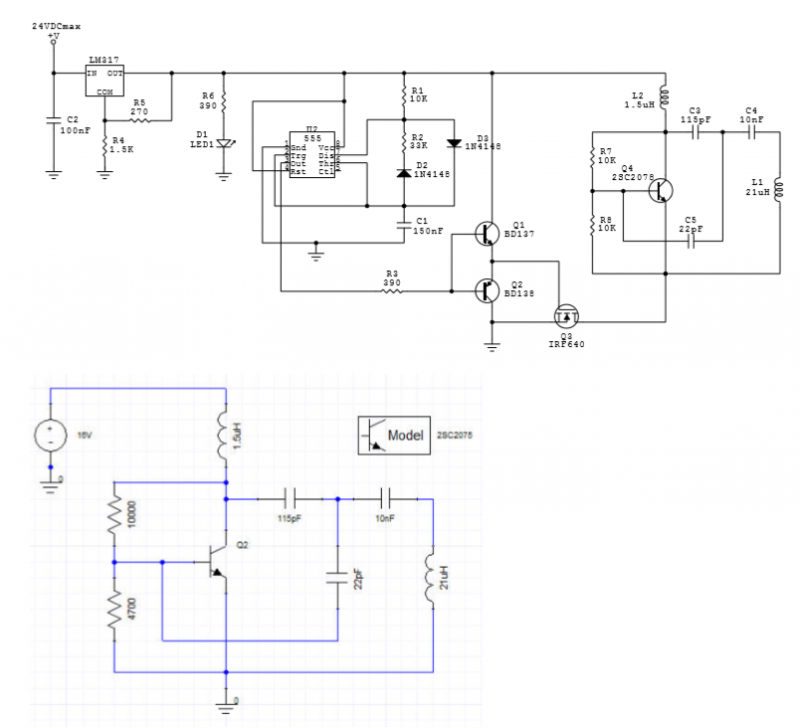
An LC oscillator is driven by pulses generated by a 555 IC-based oscillator. The LC oscillator is constructed around a 2SC2078 transistor. The circuit diagram is illustrated in Fig. 1, along with an Ansoft Designer simulation. The measured and...
The RF design and construction of radio frequency oscillators. Radio frequency (RF) oscillators are essential components in various electronic systems, generating signals at specific frequencies used for communication, signal processing, and other applications. The design of RF oscillators involves several...
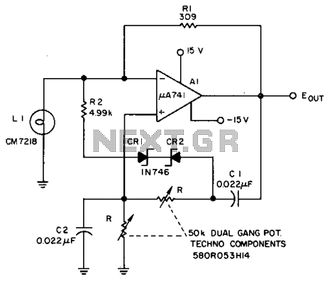
The Lamp LI stabilizes the loop gain at higher frequencies, while the limiting action of R2, CRI, and CR2 prevents clipping at low frequencies and increases the frequency adjustment range from approximately 3:1 to over 10:1. Additionally, waveform purity...