
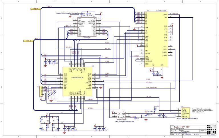
Global Positioning System GPS
The GPS system architecture is designed to provide reliable and accurate positioning information. The satellites operate in a constellation that allows for continuous coverage of the Earth's surface. The GPS receiver's ability to triangulate its position based on signals from multiple satellites is a fundamental aspect of its operation. The receiver uses a technique called trilateration, which involves calculating the distances to each satellite based on the time it takes for the signals to travel from the satellites to the receiver. This distance measurement is affected by various factors, including atmospheric conditions and signal obstructions.
For optimal performance, the GPS receiver should be calibrated and maintained properly. The use of an active antenna is recommended to amplify weak signals, especially in environments where satellite visibility is limited. Furthermore, the integration of WAAS technology in compatible receivers enhances accuracy by correcting errors in the GPS signals. The acquisition process is critical for the receiver to establish an initial position fix, which can be expedited by having prior knowledge of the receiver's location and time.
In applications where GPS accuracy is paramount, additional measures such as differential GPS (DGPS) can be employed, which uses ground-based reference stations to provide real-time corrections to the GPS signals. Overall, the design and implementation of GPS technology involve a complex interplay of satellite technology, signal processing, and user interface considerations to ensure reliable navigation and positioning capabilities.The Global Positioning System (GPS) relies on more than two dozen GPS satellites orbiting the Earth. Each satellite transmits signals including a very precise clock plus satellite position information that allows a GPS receiver to determine its location, speed and direction. A GPS receiver calculates its position by measuring the distance between itself and three or more GPS satellites. Because the signal from the GPS satellite travels at a known speed, measuring the time delay between transmission and reception of each GPS radio signal allows the receiver to calculate the distance to each satellite. By determining the position of, and distance to, at least three satellites, the receiver can compute its position.
GPS receivers typically do not have perfectly accurate clocks and therefore track one or more additional satellites to correct the receiver`s clock error. The GPS signal is circularly polarized with a typical center frequency of 1. 575 gigahertz. For best results, an active antenna amplifies the signal before delivering it via a coaxial cable to the GPS receiver.
The GPS antenna should be mounted in a position that has a clear view of the sky so that the satellite signals can be received. GPS receivers typically do not work inside buildings, and may have trouble in vehicles or areas where the view of the sky is obstructed by tall buildings or dense foliage.
Operating in urban areas can confuse the receiver due to signal reflections off buildings that result in multipath effects that lengthen the time it takes for a signal to reach the receiver, causing errors in the reported position. Some GPS receivers have a built-in Wide Area Augmentation System, or WAAS, that improves accuracy using a network of ground stations to provide additional information to the GPS receiver.
The Garmin GPS-15 receiver on the GPS Wildcard is not WAAS enabled. When a GPS receiver is first turned on, it must go through an acquisition process to locate and lock onto the satellite signals. The more initial information the GPS has about its location and time, the faster the acquisition process.
A warm acquisition occurs when the initial receiver location, time, and satellite location (ephemeris) data is known. A cold acquisition occurs when the initial receiver location, and time is known, but the satellite location data is unknown.
If even less information is known, a sky search is required to complete the acquisition process and obtain a position fix. With the power off, connect the female 24-pin side of the stacking go-through Wildcard bus header on the bottom of the GPS Wildcard to Wildcard Port 0 or Wildcard Port 1 on the controller or its mating Docking Panel (formerly the PowerDock).
The corner mounting holes on the Wildcard should line up with the standoffs on the controller board. The Wildcard ports are labeled on the silkscreen of the controller board. Note that the GPS Wildcard headers are configured to allow direct stacking onto the controller board, even if other Wildcards are also installed. Do not use ribbon cables to connect the GPS Wildcard to the Wildcard bus. CAUTION: The Wildcard bus does not have keyed connectors. Be sure to insert the Wildcard so that all pins are connected. The Wildcard bus and the GPS Wildcard can be permanently damaged if the connection is done incorrectly.
Once you have connected the GPS Wildcard to the Wildcard bus, you must set the address of the Wildcard (also called the module number) using jumper shunts across J1 and J2. The Wildcard Select Jumpers, labeled J1 and J2, select a 2-bit code that sets a unique address on the Wildcard port of the controller board.
Each Wildcard port on the controller accommodates up to 4 Wildcards. Wildcard Port 0 provides access to Wildcards 0-3 while Wildcard Port 1 provides access to Wildcards 4-7. Two Wildcards on the same port cannot have the same address (jumper settings). These are the possible jumper 🔗 External reference
Related Circuits
This document discusses a do-it-yourself alarm system utilizing the PIC18F452 microcontroller. It is a highly engaging project, although the schematic is quite complex. The project employs three main components to create the personal alarm system. The infrared (IR) proximity...
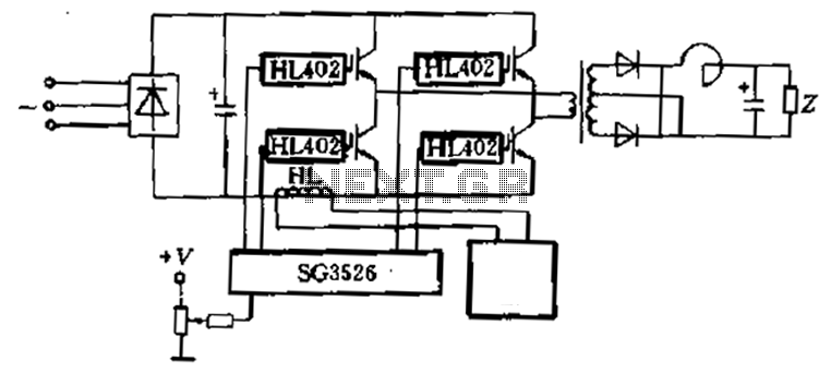
Applications are provided to complete the four-piece HL402 switching power supply system diagram, which drives four power IGBT switching power supplies. The IGBT drive pulse is generated by the SG3526. The HL component serves as a current sensor, utilized...
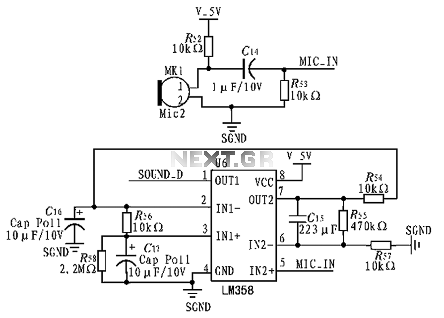
The circuit diagram focuses on the research and design features applied to mobile robots. The design considers small size, low power consumption, and ease of movement, catering to home users with a user-friendly display interface. For speech recognition, a...
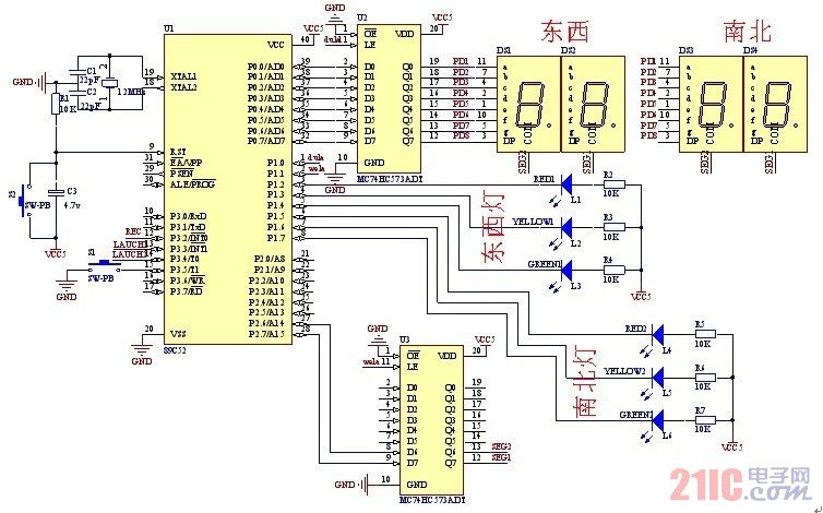
A steady, flexible, and convenient traffic light control system is essential for effective traffic management. In practice, many traffic lights operate on a time interval basis. This design allows for the adjustment of switching times for traffic lights during...
Nowadays every institution needs automation. As a part of college automation, a project has been developed for a Voice Interactive System for College Automation. This project allows users to quickly access student attendance and marks through the telephone line...

This 555 timer circuit temperature monitoring system project can monitor temperature at up to four points. The system allows for the selection of whether the alarm should be triggered when the temperature increases or decreases, depending on the resistance...
Warning: include(partials/cookie-banner.php): Failed to open stream: Permission denied in /var/www/html/nextgr/view-circuit.php on line 713
Warning: include(): Failed opening 'partials/cookie-banner.php' for inclusion (include_path='.:/usr/share/php') in /var/www/html/nextgr/view-circuit.php on line 713