
Zero Crossing Detector (ZCD): Comparator circuit using 741 op amp
%2Busing%2Bop%2Bamp%2B741%2Bic%2B.png "Zero Crossing Detector (ZCD): Comparator using 741 op amp")
The zero crossing detector (ZCD) circuit is primarily designed to identify the point where an alternating current (AC) signal crosses the zero voltage level. This is crucial in various applications, including phase-locked loops, motor control systems, and signal processing. The circuit typically employs an operational amplifier (op-amp) configured as a comparator. The op-amp compares the input AC signal with a reference voltage, usually set to zero volts. When the input signal exceeds this reference voltage, the output of the op-amp switches to its positive saturation voltage (+Vsat), and when the input signal falls below the reference, the output switches to its negative saturation voltage (-Vsat).
In the case of the inverting zero crossing detector using the op-amp 741, the non-inverting input is connected to the ground (0V), while the inverting input receives the input signal. The output of the op-amp will toggle between +Vsat and -Vsat based on the input signal's polarity. The circuit can be visualized with a simple schematic that includes the op-amp, resistors for feedback and input, and the output connected to an indicator or another control circuit.
This configuration is beneficial for signal conditioning, where the ZCD can clean up noisy signals by providing a clean square wave output that can be easily processed by digital circuits. Furthermore, the ZCD can be employed in applications such as frequency counters, where it detects the frequency of an input signal by counting the number of zero crossings in a given time frame. In power electronics, it serves as a critical component for switching applications, allowing for precise control of power devices based on the input signal's characteristics.
In summary, the zero crossing detector is an essential circuit in both analog and digital electronics, providing a reliable means of detecting signal transitions and enabling various applications ranging from signal processing to power control.Zero crossing detector(ZCD) is a voltage comparator that switches the output between +Vsat and Vsat (Vsat: Saturation voltage almost equal to 14V) when the input crosses zero reference voltage. Then what is a comparator In simple words comparators are basic operational amplifier circuits that compare two voltages simultaneously and switches th
e output according to the comparison. We can say zero crossing detection circuit is a comparator example. We will discuss in detail about comparator in our upcoming articles. Inverting zero cross detector circuit schematic using op amp 741 IC is shown below along with working, input output wave forms. ZCD circuit can be used to check whether the op-amp is in good condition. Zero crossing detectors can be used as frequency counters and for switching purposes in power electronics circuits.
ZCD is a basic op amp circuit. 🔗 External reference
Related Circuits
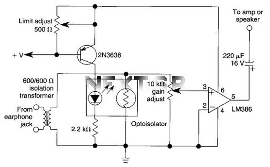
An optoisolator is utilized as an attenuator in this circuit. When the LM386 draws more current from audio signals, the 2N3638 activates, which biases the optoisolator on, thereby reducing the volume. The circuit employs an optoisolator to achieve signal attenuation,...
This design schematic represents a Class A power amplifier. It closely matches the operating parameters of Class B to facilitate comparison, particularly with a negative feedback (NFB) factor of 30dB at 20 kHz. The front end is similar to...
The input stage is critical for common-mode rejection and noise performance. A Burr-Brown INA121 differential amplifier is utilized, configured for a gain of 10. The input stage is DC coupled, and with a 9-volt supply, it can tolerate a...
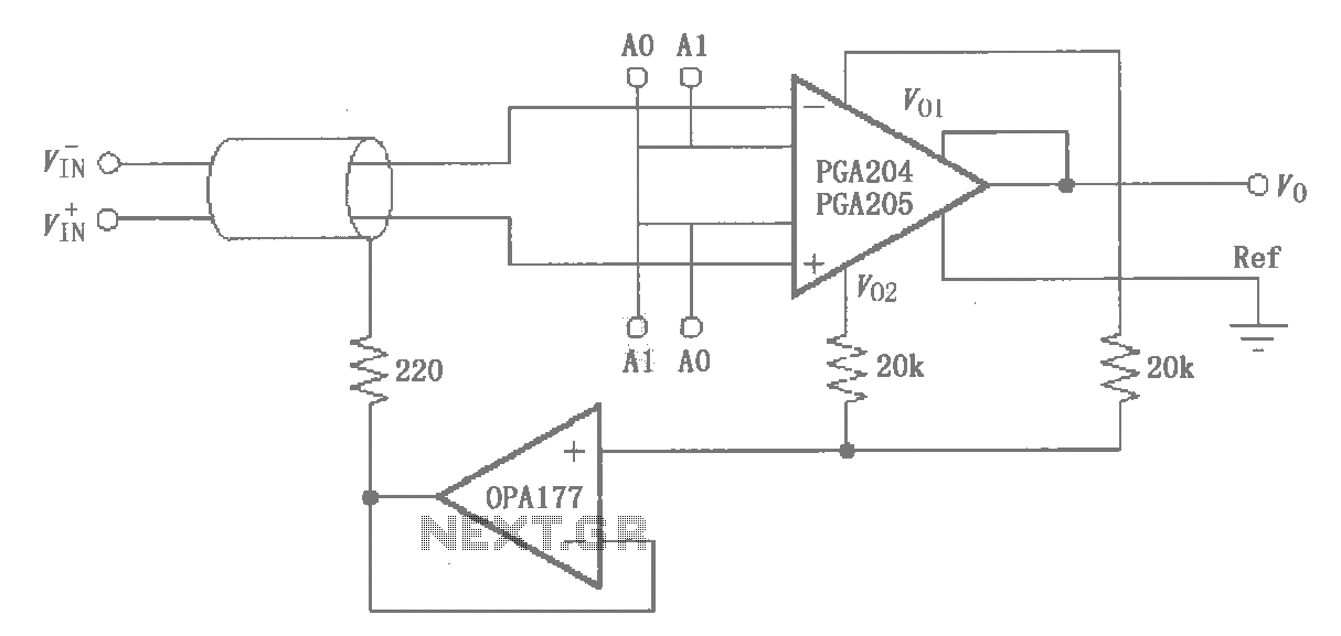
The circuit illustrated by the PGA204/205 pertains to the shield drive circuit shown in the figure. It is demonstrated through interference theory and practical application that the cable shield, when transmitting weak signals, maintains a certain potential. This configuration...
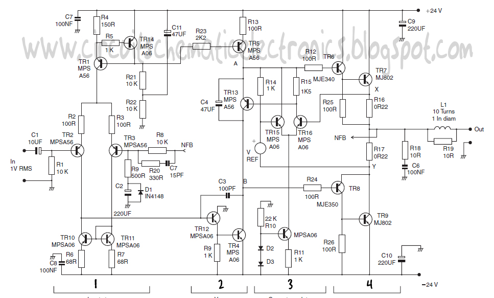
Here I propose a project of an AB class power amplifier, at its simplest, assembled with common components (not very expensive), based on traditional diagrams: a symmetrical differential input stage, a cascode stage driver, and a MOSFET output stage....
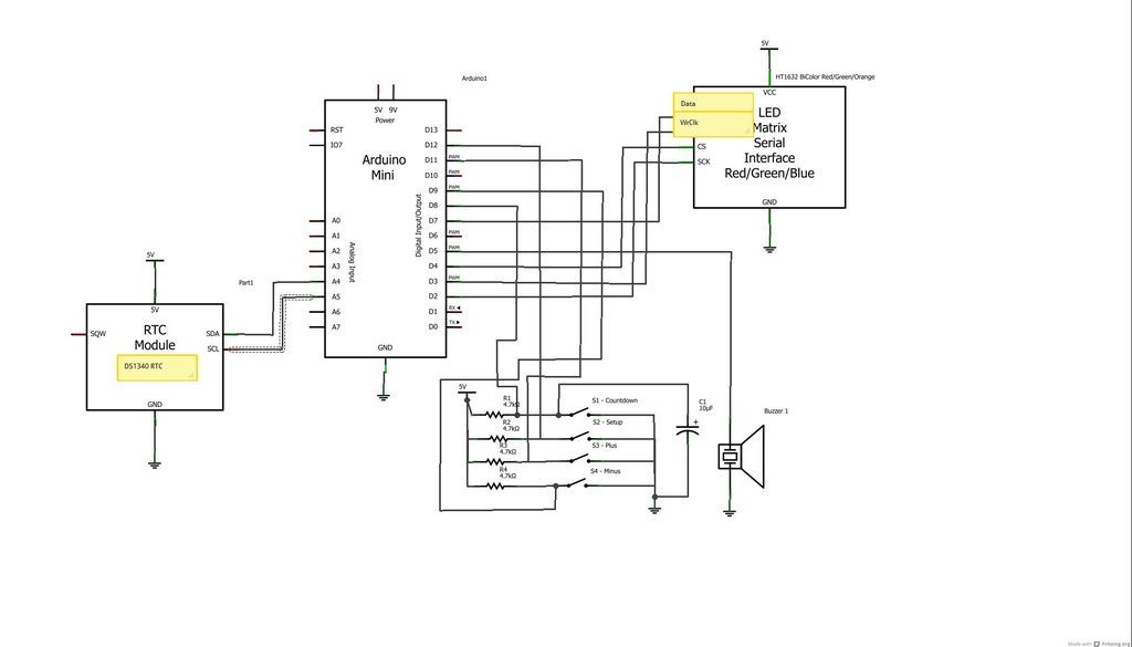
The device is designed to promote respectful time management during meetings, particularly useful in ship-room or SCRUM meetings. The following is a list of components required, including links for purchasing specific parts. It is advisable to check eBay or...