
guild brian may box

The circuit design features a Cornish buffer, which serves to maintain signal integrity and drive capability, ensuring that the subsequent treble booster operates effectively. The buffer is typically implemented using a high-quality operational amplifier (op-amp) configured for unity gain, providing a low output impedance while preserving the tonal characteristics of the input signal.
The treble booster, associated with Brian May, is designed to amplify high-frequency signals, enhancing the brightness and clarity of the guitar tone. This stage may utilize discrete transistor configurations or specialized ICs optimized for high-frequency response. The interaction between the buffer and the treble booster is crucial, as the buffer allows for a consistent input impedance, which can affect the overall tonal response of the booster.
The layout of the circuit is essential for minimizing noise and interference. Careful routing of the input and output signals, along with proper grounding techniques, will help ensure that the circuit performs optimally. The SPDT switch configuration allows for seamless switching between the buffered and bypassed states, while the optional DPDT switch can facilitate an LED indicator to visually confirm the circuit's active state.
In summary, this circuit combines the benefits of a Cornish buffer with a Brian May treble booster, providing a unique tonal enhancement for guitarists seeking to achieve a distinctive sound. Proper implementation of the components and layout will result in a reliable and high-performance effect pedal.This is a bit of an unusual one because I`m not even sure what it is. It`s based on a schematic done by Analogguru and is obviously a Cornish buffer in front of a booster, so what I am assuming is that the Guild Brian May is the treble booster, and the whole circuit amounts to the modifications done by Pete Cornish when putting the effect in one o f his boards for Brian. Some or all of that may be wrong as it is just my assumption, so please correct me if anyone knows more, but the thought of a Cornish buffer into a Brian May treble booster seemed too good an opportunity to miss so I thought I`d have to do the layout! :o) The input socket should be taken directly to the board input and so only a SPDT stomp is needed for the switching because the buffer remains in circuit during bypass (the stomp is the "Sw#" connections shown in the layout).
You will of course need a DPDT stomp if you want to include an LED. For those wanting true bypass instead of the Cornish buffer. shame on you! :o) 🔗 External reference
Related Circuits
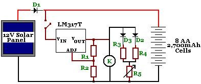
The circuit is designed to power a CCTV camera, provide lighting inside a nestbox, and charge batteries using a photovoltaic (PV) solar panel. It includes a circuit diagram for a solar-powered wireless CCTV camera with battery backup. D1 is...
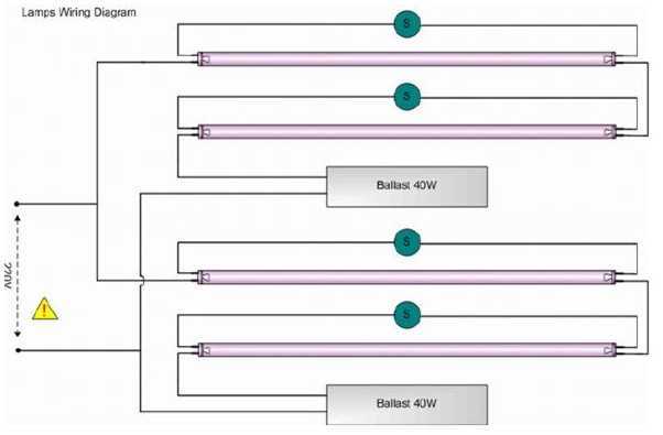
Four blacklight lamps, 15W each, emit radiation in the UVA region, with a peak around 350nm where the thin surface above the copper of the photosensitive board is sensitive. The lamps are taken by two and are connected in...
A stomp-box was designed and built for Grammy-winning resophonic guitar player Stacy Phillips. He typically uses two transducers on his Dobro-style instruments: a piezo element mounted internally and a gooseneck-mounted electret microphone positioned approximately one inch above the resonator...
This circuit creates a buzz coil using a standard automotive ignition coil. A 556 dual timer is employed to establish the frequency and duty cycle of the coil current. One timer functions as an oscillator to generate the 200...

The LS3404 melody chip is activated when the hold switch (SI) is pressed, causing SCR1 to conduct and maintain the telephone line through Tl, Rl, and LED1. The voltage across Rl and LED1 is utilized to power the melody...
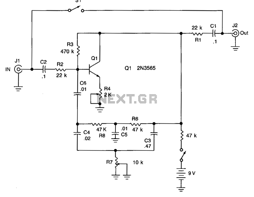
Adjusting potentiometer R7 introduces additional tonal variation from low to high frequencies. To configure the unit, adjust potentiometer R4 until an oscillation or whistle is heard, then reduce R4 until the oscillation stops. The tonal effect can be modified...