
Guitar and bass tuner

The circuit design incorporates a top-octave generator (IC2) which is pivotal in synthesizing a range of musical notes. The 50240 chip generates a complete set of twelve notes based on a single frequency input, facilitating the creation of harmonically rich sounds essential for musical applications. The input frequency is generated by an oscillator formed from two sections of the 4001 quad 2-input NOR gate (IC1), allowing for precise frequency control and modulation through the trimmer potentiometer (R2). This flexibility enables users to adjust the pitch output to suit various musical contexts.
Frequency division is accomplished by the dual D flip-flops (IC3-IC7), which effectively reduce the frequencies produced by the top-octave generator to create the necessary lower frequencies for bass pitch references. The output from these flip-flops is then routed through isolation diodes (D1-D12), ensuring that each note remains distinct and free from interference, which is crucial for maintaining sound quality in musical applications.
The TONE switch (S3) allows for user interaction with the generated signals, enabling the selection of different tones. The audio power amplifier (IC8, LM386) amplifies the pitch reference signal, with R7 serving as a volume control, allowing the user to adjust the output level. Similarly, the second LM386 (IC9) amplifies the signal from the instrument being tuned, with R10 providing further volume control.
The outputs from both amplifiers are coupled to a headphone jack (J1) through capacitors (C5 and C12), ensuring that the audio signals are appropriately filtered to prevent DC offsets from reaching the headphones. The S2 switch offers a choice between stereo and mono output, allowing for versatile audio configurations depending on user preference or specific application requirements.
Finally, the circuit is powered by eight "AA" cells arranged in series, providing a reliable power source for sustained operation. This design ensures that the circuit remains portable and user-friendly, making it suitable for various tuning and musical applications.The heart of the circuit is IC2, a 50240 top-octave generator. That device uses a single input-frequency to generate all twelve notes of the musical scale. The input signal is provided by IC1, a 4001 quad 2-input NOR gate. Two sections of that IC are used to form an oscillator that runs at approximately 2 MHz. The frequency can be adjusted by trimmer potentiometer R2. Dual D flip-flops, IC3-IC7, are used as frequency dividers. They divide down the upper-octave frequencies from IC2, thus generating the lower-frequency notes required for the pitch references. The chords for the bass pitch-references are composed of three notes each. Those notes are taken from various outputs of IC2-IC7 through isolation diodesD1-D12. All signals are routed to the TONE switch, S3. The wiper arm of that switch is connected through R7 to the input of audio power-amplifier IC8, an LM386. The resistor acts as a volume control for the pitch reference. Another LM386, IC9, serves as an amplifier for the instrument being tuned, with RIO acting as its volume control.
The outputs of IC8 and IC9 are coupled, through C5 and C12 respectively, to the headphone jack, J1. Switch S2 STEREO/MONO is used to mix the reference and instrument signals at IC9 for mono operation. Power is supplied by eight "AA" cells connected in series.
Related Circuits
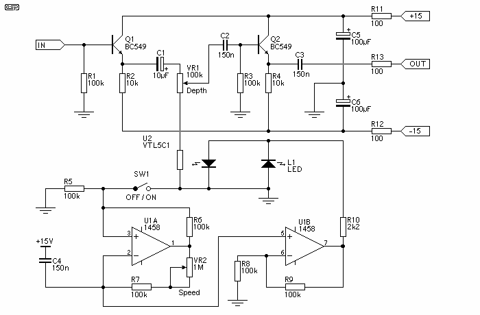
The unit is simple to build, and does not need really low noise opamps, since they only act as a modulator oscillator. I used 1458 dual types in the prototype, and they are more than good enough. The transistors...
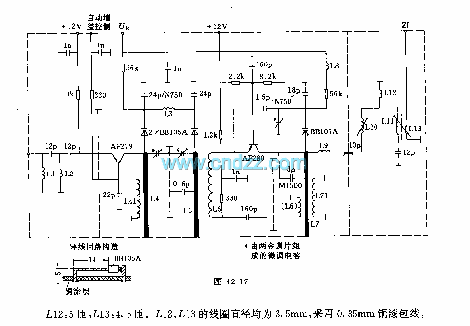
The circuit features an adjustable prestage utilizing the AF279 transistor, while the natural oscillation mixer stage employs the AF280 transistor. The power circuit is mounted on a board with copper coating. The main coil specifications are as follows: L1,...
For long-distance listeners (DX-ers), it is a pleasure to tune into an 8 MHz wide band that is typically unoccupied but can provide periods of clear reception during the Sporadic E season from various distant countries. Usually, only one...
After testing various circuits, the simplest design was developed, characterized by minimal parts count and straightforward signal flow, reminiscent of "Heathkits." This design features a single tone control and an FET buffer. Modern elements include True Bypass switching, a...
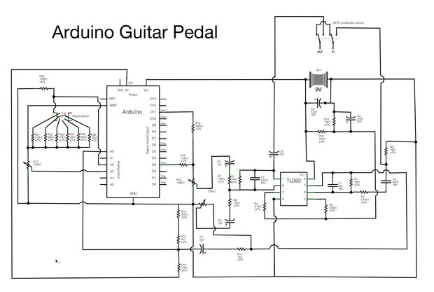
Begin constructing the circuit as illustrated in the schematic. To view the schematic in a larger format, click the small "i" icon located in the upper right corner of the image. The schematic serves as a visual representation of the...
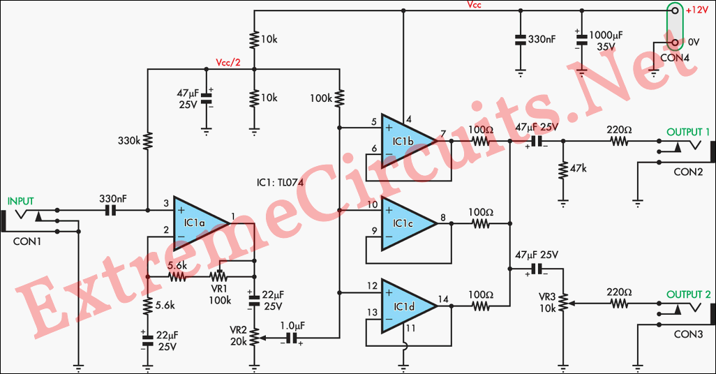
Magnetic pickups in musical instruments exhibit a relatively high output impedance, which can lead to a decrease in treble response when connected through long cable runs or to equipment with low input impedance. This preamplifier addresses these challenges by...