
TIMER IS AUTOPATCH KEYER

The described circuit operates as a versatile frequency detection and response system, incorporating several critical components that enhance its performance and functionality. The Colpitts oscillator serves as the core frequency-generating element, responding dynamically to the proximity of metallic objects. The use of a 565 Phase-Locked Loop (PLL) allows for precise frequency measurement, which is essential for applications requiring accurate detection of frequency shifts.
The voltage-to-frequency converter is notable for its high linearity and stability, making it suitable for precision applications. The LTC1052's feedback mechanism ensures that variations in input voltage are effectively translated into corresponding frequency changes, maintaining a high degree of accuracy across its operational range. The temperature coefficient of 20 ppm/°C indicates that the circuit can maintain its performance across varying temperatures, which is crucial for outdoor or industrial applications.
In the receiver section, the integration of a PC1373 IR remote-control preamplifier ensures that the circuit can effectively capture and process remote control signals within the specified frequency range. The automatic gain control feature allows the system to adapt to varying signal strengths, ensuring reliable operation in diverse environments. The use of a Schmitt trigger provides noise immunity and signal conditioning, resulting in a clean, squared output suitable for digital processing.
The 567 tone decoder plays a pivotal role in identifying specific frequencies, enabling the system to respond only when the desired signal is present. The subsequent stages, including the D flip-flops and inverters, form a robust control mechanism that activates the relay, allowing for the switching of external devices based on the detected signals. This design showcases a well-integrated approach to frequency detection and control, suitable for a variety of applications, including remote control systems and automated switching devices.Frequency change produced in Colpitts oscillator by metal object near tank coil is indicated by 565 PLL connected asfrequency meter. Oscillator frequency increases when search coil is brought near nonferrous metal object. Oscillator frequency decreases, as indicated by lower meter reading, when coil is brought nearferrous object.
Signetics Analo g Data Manual, ``Signetios, Sunnyvale, CA, 1977, p 856 858. (View) This stabilized voltage-to-frequency converter features 1 Hz-1. 25 MHz operation, 0. 05% linearity, and a temperature coefficient of typically 20 ppm/ °C. This circuit runs from a single 5-V supply. The converter uses a charge feedback scheme to allow the LTC1052 to close a loop around the entire circuit, instead of simply controlling the offset. This approach enhances linearity and stability, but introduces the loop`s settling time into the overall voltage-to-frequency step-response characteristic.
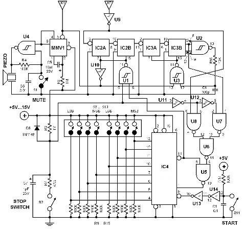
(View) This receiver is built around a PC1373 IR remote-control preamplifier, a sensitive 30-to-40 kHz tuned detector, an autoniatic gain control, a peak detector, and an output waveshaping buffer. The demod-ulated signal from the preamp stage is sent to IC4A, a 74C14 Schmitt trigger. The squared-up 1 500-Hz signal is then sent to the clock input of IC5A, half of a 4013 dual D flip-flop.
That 750-Hz signal is clipped to approximately 0. 7-V p-p by diodes D3 and D4. The clipped signal is then fed to IC6, a 567 tone decoder. The output of that IC goes low whenever the frequency of the signal fed to it is within the lock range of its internal VC0. When IC6 detects a signal of the proper frequency, pin 8 goes low. The output signal is fed through another Schmitt trigger (IC4B), which drives another D flip-flop, IC5B.
Schmitt trigger IC4B also drives IC4C, which in turn drives LED4, SIGNAL, which fights up whenever a signal is received. The Q output of IC5B drives two parallel-connected inverters. IC4C and IC4F turn transistor Q2 on when Q goes low. That transistor energizes the relay; its contacts switch the controlled device on and off. (View) This circuit can accept positive or negative or differential control voltages. The output frequency is zero when the control voltage is zero. The 741 op amp forms a current source controlled by the voltage EC to charge the timing capacitor C1 linearly.
NE555 is connected in the astable mode, so that the capacitor charges and discharges between 1/3 VCC and 2/3 VCC. The offset is adjusted by the 10-K potentiometer so that the frequency is zero when the input is zero.
For the component values shown: f‰ 4. 2 EC kHz. If two dc voltages are applied to the ends of R1 and R4, the output frequency will be proportional to the difference between the two voltages. (View) This receiver is built around a PC1373 IR remote-control preamplifier, a sensitive 30-to-40 kHz tuned detector, an autoniatic gain control, a peak detector, and an output waveshaping buffer.
The demod-ulated signal from the preamp stage is sent to IC4A, a 74C14 Schmitt trigger. The squared-up 1 500-Hz signal is then sent to the clock input of IC5A, half of a 4013 dual D flip-flop. That 750-Hz signal is clipped to approximately 0. 7-V p-p by diodes D3 and D4. The clipped signal is then fed to IC6, a 567 tone decoder. The output of that IC goes low whenever the frequency of the signal fed to it is within the lock range of its internal VCO.
When IC6 detects a signal of the proper frequency, pin 8 goes low. The output signal is fed through another Schmitt trigger (IC4B), which drives another D flip-flop, IC5B. Schmitt trigger IC4B also drives IC4C, which in turn drives LED4, SIGNAL, which fights up whenever a signal is received.
The Q output of IC5B drives two parallel-connected inverters. IC4C and IC4F turn transistor Q2 on when Q goes low. That transistor energizes the relay; its contacts switch the controlled device on and off. (View) The portable charger is intended pri 🔗 External reference
Related Circuits
A relay (RL1) is activated with a 100-second delay when a +12V power supply is connected to the circuit. Figure 2 illustrates a relay timer circuit utilizing a 555 timer, featuring two time ranges: 6-60 seconds and 1-10 minutes...
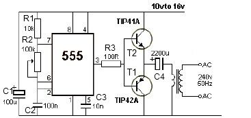
12V power inverter circuit utilizing a 555 timer for an electronic project. The 12V power inverter circuit is designed to convert a DC voltage of 12 volts into an AC voltage suitable for powering small electronic devices. The core component...
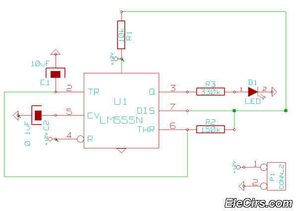
This is a very simple 555 timer circuit that serves as a straightforward theft deterrent, which may be just as effective. The idea is to have a flashing red LED indicate that your car is protected. This device can...
The time interval of this circuit can be varied digitally through the DIP switches. The time code must be set in BCD form. A 120 Hz signal generated by doubling the line frequency is used as the time reference....
A very long time constant is provided by R1 and C1. C1 discharges, and the near-zero voltage at its positive lead is applied to the high-impedance inputs of the circuit. In this circuit, the combination of resistor R1 and capacitor...
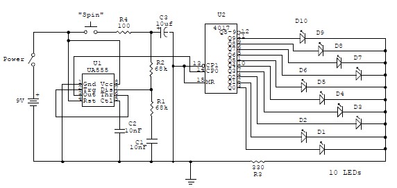
This electronic circuit is a simplified version of an electronic roulette game, utilizing the 4017 integrated circuit (IC), which functions as a 10-stage decade counter/divider. It is driven by a versatile 555 IC configured as a voltage-controlled oscillator (VCO)....