
h bridge

The H-bridge motor control circuit is an essential configuration for driving DC motors in both forward and reverse directions. It utilizes four power MOSFETs arranged in a bridge configuration, allowing for bidirectional control of the motor.
In this setup, two pairs of MOSFETs are used: one pair for controlling the current flow in one direction and the other pair for the opposite direction. The gates of the MOSFETs are driven by a microcontroller or a PWM signal, enabling precise control over the motor speed and direction.
The operation of the H-bridge can be summarized as follows: when the upper left and lower right MOSFETs are turned on, the current flows through the motor in one direction, causing it to rotate clockwise. Conversely, when the upper right and lower left MOSFETs are activated, the current reverses, and the motor rotates counterclockwise.
To prevent short circuits and ensure safe operation, it is crucial to implement dead time between switching the MOSFETs. This dead time allows one MOSFET to turn off completely before the opposite pair is activated. Additionally, flyback diodes are often included in the circuit to protect the MOSFETs from back EMF generated when the motor is de-energized.
The selection of appropriate MOSFETs is vital, as they must handle the motor's current and voltage ratings. Proper heat dissipation methods, such as heat sinks or active cooling, should also be considered to maintain the reliability of the circuit during operation.
Overall, the H-bridge motor control circuit not only provides a practical application for power MOSFETs but also serves as a foundational learning tool for understanding motor control techniques in electronic design.Learning how to use power MOSFETs by building an H-bridge motor control.. 🔗 External reference
Related Circuits
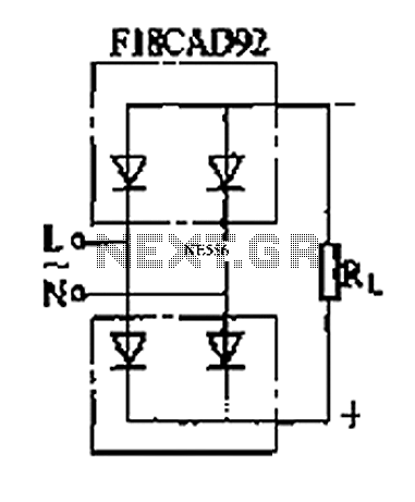
The circuit depicted is a single-phase bridge rectifier. It consists of arms with a cathode (negative electrode) and parallel anodes (positive electrodes) arranged in a configuration that connects multiple rectifier modules to form a bridge, commonly referred to as...
For a project such as a robot or car, an electronic circuit is required, controlled by a control circuit. This control circuit outputs signals to manage an H-Bridge. The circuit includes a Hex Bug design, where the control circuit...
Incandescent lamp has been used to reduce harmonic distortion in sine oscillator circuit. The nonlinear resistance characteristic of the lamp filament help the circuit to shape the signal to approximate the ideal sine wave. Here is the classic Wien-bridge...
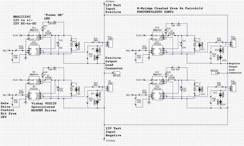
The Murata NMC1215SC DC/DC converters in a CPU-controlled H-Bridge design are experiencing repeated failures, with no obvious signs of the cause. The Murata NMC1215SC is a step-down DC-DC converter renowned for its efficiency and compact design, making it suitable for...
The circuit was designed to create an electronic oscillator known as a Wien Bridge Oscillator, which can be used for the creation of low-frequency sine waves. The Wien Bridge Oscillator is a type of electronic oscillator that generates sine waves....
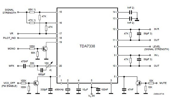
An FM stereo decoder can be designed using the TDA7388A, which features a compact design. This FM stereo decoder schematic circuit utilizes the TDA7388 integrated circuit, produced by ST Microelectronics. The TDA7388 is a monolithic integrated stereo decoder equipped...