
Arms single-phase rectifier bridge rectifier circuit

The single-phase bridge rectifier circuit is a fundamental electronic configuration that converts alternating current (AC) into direct current (DC). The circuit typically consists of four diodes arranged in a bridge topology. This arrangement allows both halves of the AC waveform to be utilized, providing a more efficient conversion compared to half-wave rectification.
In this configuration, the AC input is connected to the two opposite corners of the bridge, while the output is taken from the other two corners. During the positive half-cycle of the AC input, two diodes become forward-biased, allowing current to flow through the load in one direction. Conversely, during the negative half-cycle, the other two diodes conduct, maintaining the same direction of current through the load. This results in a pulsating DC output.
The bridge rectifier circuit is commonly employed in power supply applications, where it is essential to convert AC mains voltage to a usable DC voltage for various electronic devices. Additional components, such as filter capacitors, are often included in the design to smooth the pulsating DC output, reducing ripple voltage and providing a more stable DC supply. The selection of diodes is critical, as they must be rated to handle the peak inverse voltage (PIV) of the AC source and the maximum load current.
Overall, the single-phase bridge rectifier circuit is a vital component in power electronics, enabling efficient power conversion and facilitating the operation of numerous electronic devices. As shown for the single-phase bridge rectifier arms rectifier circuit. The circuit consists of arms cathode (negative electrode) and arms parallel anode (positive electrode) in parallel rectifier modules, circuits connected to form a bridge, so called bridge rectifier circuit.
Related Circuits

The circuit requires a power source to function. The PIC needs a 5-volt supply, while the driver demands a higher voltage to operate the motors. Inputs: The inputs come from three sensors. Two of these sensors are Light Dependent...

You have 4 transistors, wired as ON OFF switches. Two signal lines allow you to run the motor in one direction, when reversed, the motor runs in the other direction. It's very straightforward to use and build, but be...
This schematic represents an FM transmitter capable of delivering an output power of 3 to 3.5 W, operating within a frequency range of 90 to 110 MHz. While the stability of the circuit is acceptable, the integration of a...

Individuals engaged in the experimentation or development of USB-connected peripheral hardware often find it frustrating to repeatedly disconnect and reconnect the plug to reestablish communication with the PC. This procedure is necessary, for instance, every time the peripheral device...
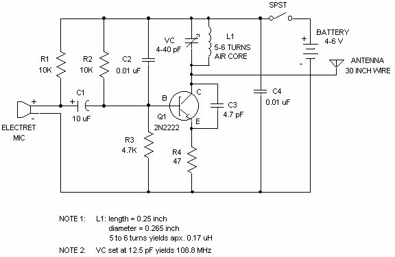
Wireless FM Transmitter. The site provides some explanation on how the circuit operates; however, there are uncertainties regarding certain components, including the electret microphone and the frequency modulation process. The electret microphone operates at a current of 200 µA,...
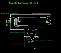
This is a simple intercom circuit utilizing the common IC LM380. In this configuration, the switch is set to the talk position for the speaker on the left, while the other participant is in the listening position. If the...