
designing audio circuit tape delay

The circuit design for a tape delay unit involves several key components and considerations to achieve the desired functionality. The tape heads, specified as cassette tape heads, will require appropriate biasing and signal conditioning to ensure optimal performance. The write head should be driven with a voltage of about 1V, which can be achieved using a simple transistor amplifier circuit, such as a common emitter configuration, to provide the necessary gain and drive capability.
For the read head, which outputs approximately 10mV, a low-noise amplifier (LNA) can be employed to boost the signal to a more manageable level for further processing. This can be accomplished using an operational amplifier (op-amp) configured for non-inverting amplification, with the gain set to achieve the desired output level. The feedback signal from this stage can then be routed to a secondary amplifier stage to achieve the required doubling of the amplitude.
The mixer stage will require a summing amplifier configuration, which can be constructed using an op-amp. This stage will combine the processed signal from the tape read head with the dry input signal. By incorporating variable resistors (potentiometers) at each input, the amplitude of both signals can be adjusted, allowing for a seamless transition between wet and dry outputs.
To ensure that the final output meets the specifications, the output stage should be designed to have an impedance of around 300 ohms. This can be achieved by using a buffer amplifier, such as a voltage follower configuration, which will provide the necessary current drive while maintaining the desired output voltage level of approximately 0.5V.
In terms of component selection, it is advisable to use low-noise and high-fidelity components to maintain audio quality throughout the signal chain. Additionally, careful attention should be paid to power supply decoupling and grounding practices to minimize noise and interference.
If adapting a tube-based circuit to a transistor configuration, it is essential to understand the differences in operating principles and characteristics between the two technologies. Transistors can replicate many of the functions of tubes, but circuit parameters such as biasing, gain, and frequency response may need to be adjusted to achieve similar performance.
Overall, while the project presents challenges, it is certainly within the realm of possibility for a medium-level hobbyist to successfully design and build a tape delay circuit with the specified requirements. With proper planning, component selection, and a willingness to experiment, the desired outcome can be achieved.Hi, this is my first post here. For the past few days I`ve been building a tape delay unit. Mechanically, it works well, but I still need to design a circuit to link all the parts together. This is, however, beyond my current level of ability, and I was wondering If I could get help. The tape heads are cassette tape heads, and have a resistance of around 300 ohms, and an inductance of 80mH. I`d like to be able to drive the write head to around 1V, and the read head will output something on the order of 10mV. It should also be possible to amplify the feedback signal to a level about twice the amplitude of the input signal.
The mixer should mix the signal from the tape read head with a dry signal from the input, and it should be possible to control the amplitude of these signals allowing the result to be fully wet or dry. The output should be approximately line level, with an output impedance of around 300 © with a peak voltage around 0.
5V. I understand what I am asking is quite complex, but is this project impossible for a medium level hobbyist with plenty of free time Is anyone an expert in this area Does anyone have any tips on how to design and build a circuit like this Thanks. While I`d definitely follow this path if I was short on time or ambition, at the moment I really just want to make this work.
It`s already been such an education so far and it`s only been a few days. While looking through some more schematics, I found one that seemed like it would be a lot easier to produce and understand. It does, however, use tubes rather than solid state components. Is there any way I could change the circuit to work with transistors Here is the schematic; That`s the site I posted the link to above already (didn`t you try clicking on it ), I specifically posted the link to a simple IC circuit, but there are transistor ones and valve ones there as well.
I did look at that circuit in detail, but it seemed like the schematic I posted might be easier for me to build, if transistors could be used instead of valves. 🔗 External reference
Related Circuits
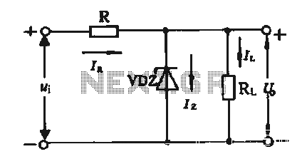
The simple voltage regulator circuit consists of a silicon regulator and a resistor. It is designed to rectify and filter DC voltage, as illustrated in the accompanying figure. The voltage regulator is connected in parallel with the load, and...
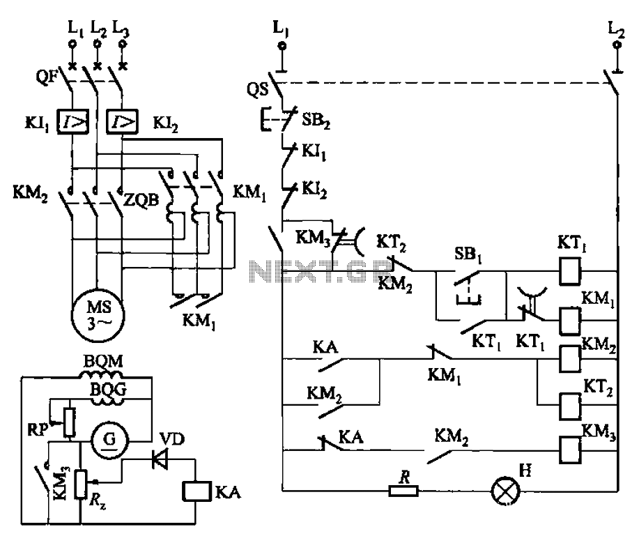
The circuit depicted in Figure 3-187 illustrates the operation of an auto step-down transformer (ZQB). Upon activation, the ZQB transformer initiates a sequence that allows the motor to gradually increase its speed. After a predetermined delay, the ZQB ceases...
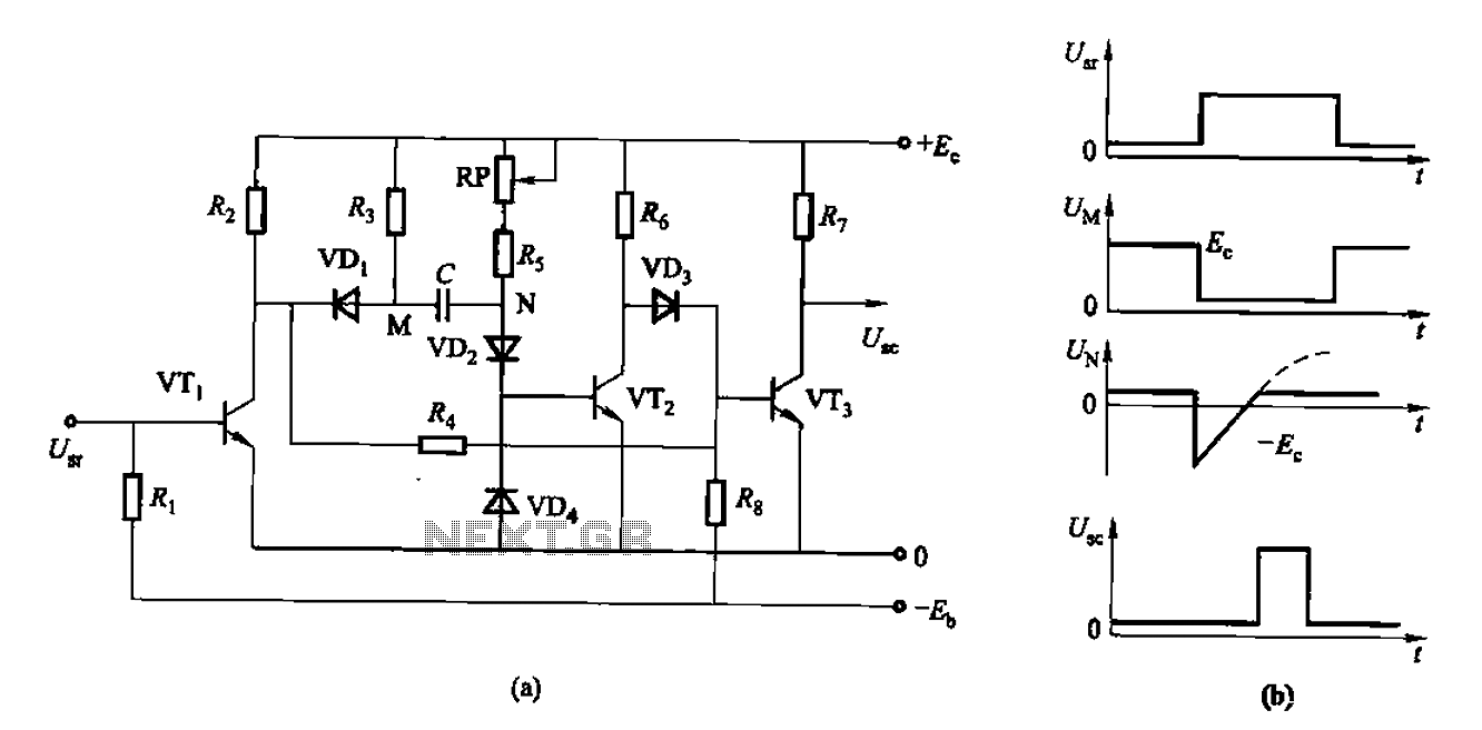
The circuit described is a discharge delay circuit that offers a longer delay compared to a standard rechargeable delay circuit, while also maintaining relatively high accuracy. The schematic diagram illustrates the input and output waveforms. Typically, when there is...
Operating radio transmitters without a license is illegal in most countries, so caution is advised with transmitter circuits. This FM low-power circuit is designed to operate within the 87-108 MHz band II, providing a range of approximately 20 to...
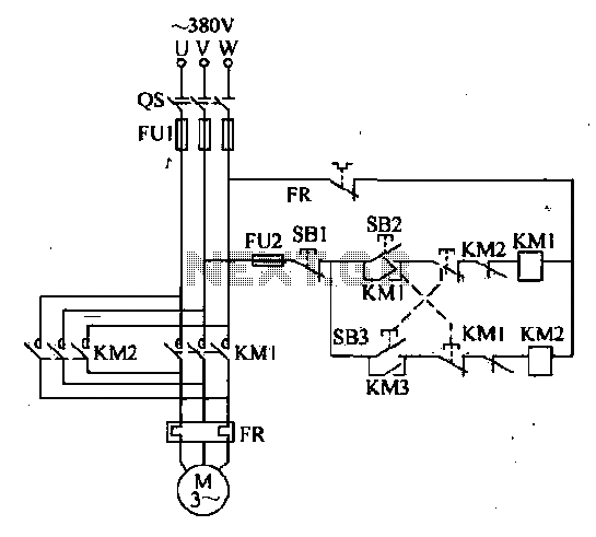
The forward and reverse dual interlock control circuit is based on the control circuit depicted in Figure 4-4, with an enhancement that incorporates a composite mechanical button interlock. The advantage of this circuit is that it allows the motor...
The circuit is capable of measuring frequencies ranging from 1.5 kHz to 500 kHz by connecting different capacitors, C1 to C6. It can handle a maximum frequency of up to 1 MHz. Transistor T1 serves as the integrator, with...