
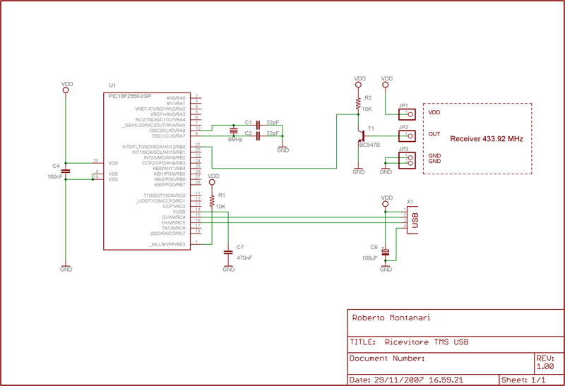
HAM Modulation Monitor

L1 - 23 Turns 24 SWG
Wound over 1.5Cm
dia PVC tube
C1 - 2J PVC Gang Capacitor
D1 - IN34 or IN4148
C2 - 0.01 ceramic disc
EP - 1 K OHMS Headphone
The Modulation Monitor circuit is designed to enable amateur radio operators (hams) to assess the quality of their transmissions without requiring a direct connection to the transmitter. This feature is particularly advantageous for ensuring optimal performance while maintaining the integrity of the transmitted signal. The circuit primarily consists of an inductor (L1), a gang capacitor (C1), a diode (D1), a ceramic capacitor (C2), and a headphone output (EP).
L1 is constructed using 23 turns of 24 SWG wire wound around a 1.5 cm diameter PVC tube, which serves as the inductor. This component is crucial for tuning into the desired frequency range, specifically the 7 MHz ham band, although it can be adjusted for other bands by modifying the values of L1 and C1. The gang capacitor C1, rated at 2J, allows for fine-tuning of the circuit's resonance, enhancing the clarity of the audio signal received through the headphones.
D1 can be either an IN34 or IN4148 diode, which plays a vital role in rectifying the incoming RF signal to audio frequencies that can be processed by the headphones. The inclusion of C2, a 0.01µF ceramic disc capacitor, aids in filtering and stabilizing the signal, ensuring that the audio output remains clean and free of unwanted noise.
For headphone connectivity, the circuit is designed to work with 1K ohm impedance headphones. However, if low impedance headphones are preferred, it is recommended to connect a suitable length of wire from the junction between the diode and the coil through a 1000pF capacitor to adapt the circuit accordingly.
The entire assembly can be conveniently housed in a plastic enclosure, allowing for easy placement near the transmitter. Proper adjustment of the gang capacitor C1 is essential to achieve maximum audio output, enabling the operator to monitor their transmission quality effectively. This simple yet effective circuit provides a valuable tool for amateur radio enthusiasts, ensuring that their communications are clear and reliable.Modulation Monitor is a simple and useful circuit for hams. You can listen to on air transmission from your rig and be sure about the quality of the transmission. It requires no direct connection with the transmitter. In the prototype, headphones of 1K impedance are used. If you want to use ordinary low impedance head phones, connect a suitable length of wire from the junction between the diode and the coil through a 1000pf capacitor.
L1 is easily available from junk box of hams since it the same as that used by hams in their QRP Transmitter. The entire setup can be housed inside a plastic box and placed near your transmitter adjust gang condenser C1 for maximum sound. The circuit is for 7 MHz ham band. Suitably changing the values of L1 and C1, it can be used for other ham bands also. L1 - 23 Turns 24 SWG Wound over 1.5Cm dia PVC tube C1 - 2J PVC Gang Capacitor D1 - IN34 or IN4148 C2 - 0.01 ceramic disc EP - 1 K OHMS Headphone
🔗 External reference
Related Circuits
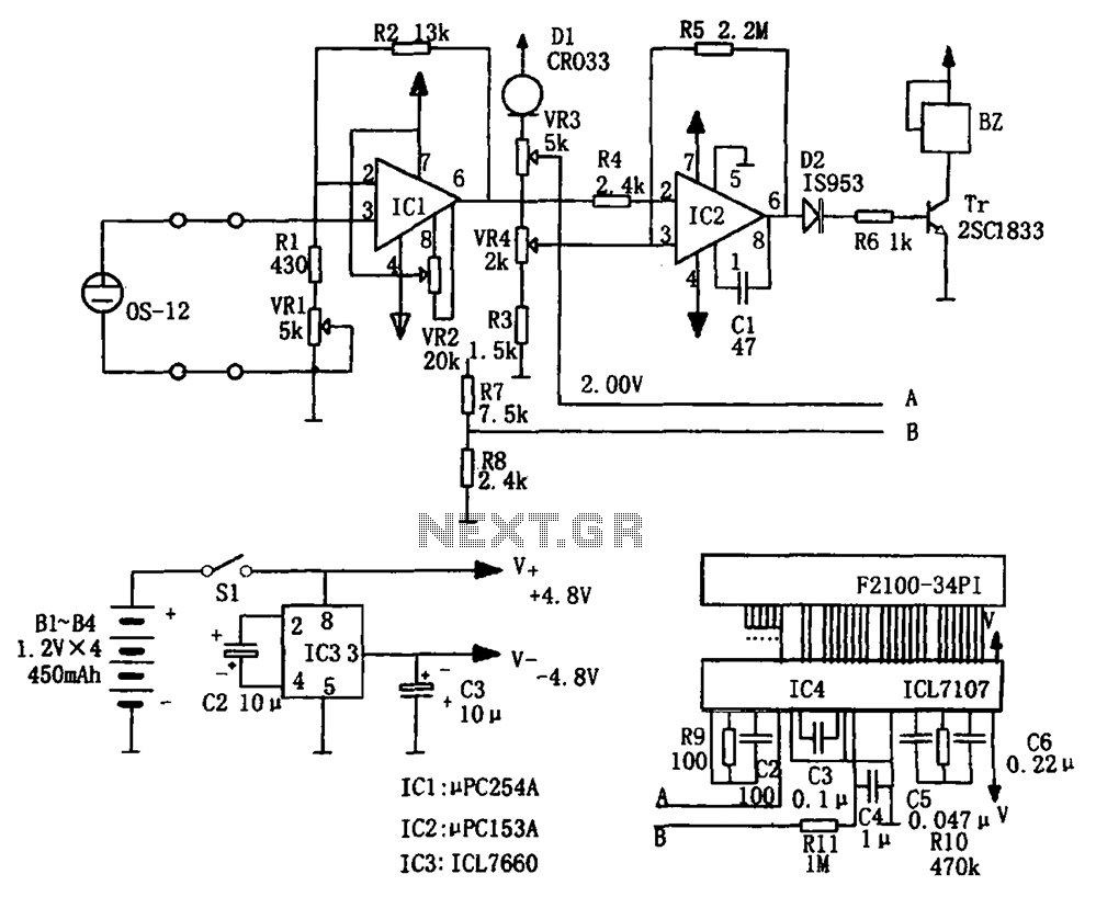
The portable hypoxia monitoring circuit comprises the oxygen sensor OS-12, a DC amplifier IC1, an A/D converter IC4, and a liquid crystal display F2100-34PI. Additionally, it includes a voltage comparator IC2 and a positive and negative power converter IC,...
This circuit can be utilized in a garden setting to detect unusual sounds or wildlife noises. It can also monitor sounds around a car parked in a remote location. The cable used for the setup can either be visible...
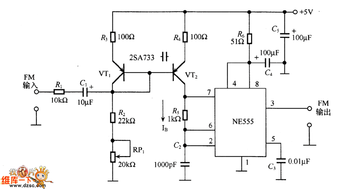
The figure illustrates an NE555 frequency modulation (FM) circuit. In this circuit, pin 7 of the NE555 is connected to an FM modulation section that consists of resistor R5 and capacitor C2, although the frequency range is somewhat limited....
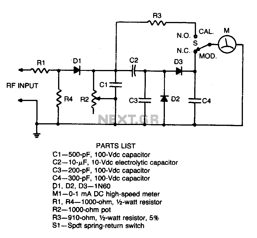
Connect this circuit to a transceiver using a coaxial T connector in the transmission line. Activate the transmitter (unmodulated), set switch 31 to CAL, and adjust resistor R2 for a full-scale reading. Return switch SI to the MOD position....
This thread explains the creation of a custom USB tire pressure monitoring system by modifying an aftermarket kit purchased on eBay. The initial step involved... The project entails the design and implementation of a USB tire pressure monitoring system (TPMS)...
Strictly speaking, this simple circuit shouldn't work! How could anyone expect an ordinary light-dependent resistor photo cell to 'see through a fingertip? This circuit utilizes a light-dependent resistor (LDR), commonly referred to as a photoresistor, which changes its resistance based...