
Tuned Radio Frequency (TRF) Receiver
 Receiver")
Superheterodyne receivers represent a pivotal advancement in radio technology, characterized by their ability to convert high-frequency signals into lower intermediate frequencies (IF) for easier processing. The fundamental operation of a superheterodyne receiver involves mixing the incoming radio frequency (RF) signal with a locally generated oscillator signal to produce the IF. This process allows for improved selectivity and sensitivity, as the IF can be amplified and filtered more effectively than the original RF signal.
The architecture of a typical superheterodyne receiver includes several key components: an antenna, a radio frequency amplifier, a mixer, a local oscillator, an intermediate frequency amplifier, and a demodulator. The antenna captures the RF signals, which are then amplified by the RF amplifier to enhance the signal strength. The mixer combines the amplified RF signal with the output from the local oscillator, creating the IF signal, which is usually at a fixed frequency, allowing for uniform processing of various RF inputs.
The local oscillator is crucial as it determines the frequency to which the incoming signal will be shifted. This frequency can be adjusted to tune into different stations. The IF amplifier further boosts the IF signal, improving the signal-to-noise ratio before it is demodulated to retrieve the original audio or data content.
Superheterodyne receivers are widely used in various applications, including AM and FM radio, television, and two-way communication systems. Their ability to handle a wide range of frequencies and provide high-quality reception makes them a popular choice in modern electronic communication systems. The evolution of superheterodyne technology has led to the development of more sophisticated designs, incorporating digital signal processing techniques to enhance performance and functionality.Superheterodyne receivers have been mass-produced since around 1924, but for reasons of cost did not become successful until the 1930s. Before the second.. 🔗 External reference
Related Circuits
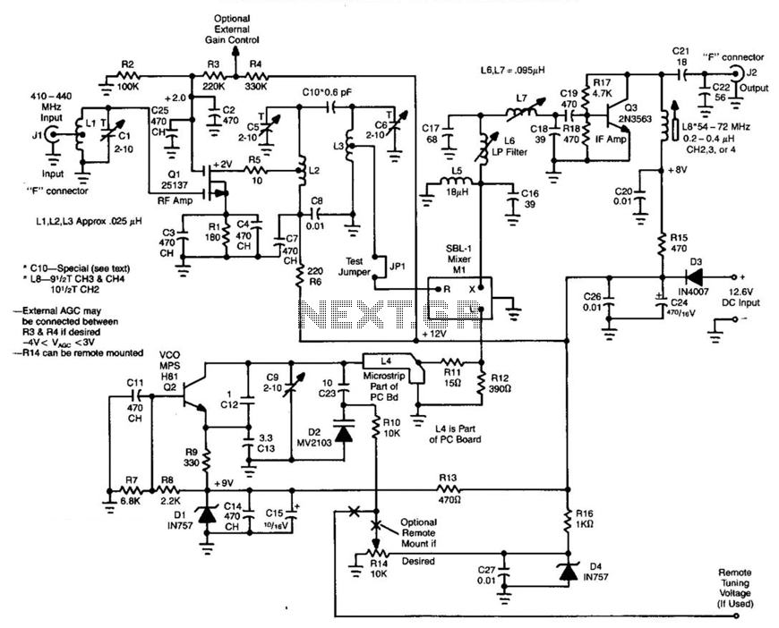
Ll, Ql, L2, and L3 form an RF amplifier stage that feeds Ml, a doubly balanced mixer. Q4 is a local oscillator stage operating in the 375-MHz range. Signals in the 420- to 450-MHz range from Ql are mixed...
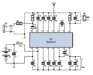
Several integrated circuits (ICs) are currently available that provide a nearly complete FM receiver solution. This project outlines a complete FM receiver circuit that offers excellent receiving and sound qualities. However, from a DIY enthusiast's perspective, the only drawback...
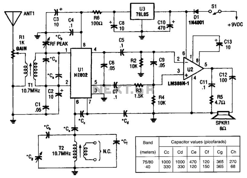
An NEC602 is utilized as a mixer with a zero intermediate frequency (IF) output, while U2 functions as an audio amplifier. This receiver is mainly designed for single sideband (SSB) and continuous wave (CW) signals. T1 and T2 are...
This is a switching circuit that provides a latching mechanism to create a set of radio buttons using push buttons. This circuit consists of an interlocking circuit. The switching circuit operates on the principle of latching, allowing multiple push buttons...
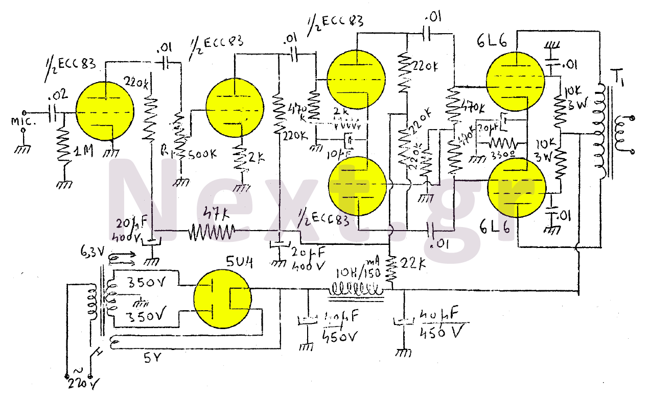
The amplifier in this design is rated at 30 Watts and is intended for use with a microphone. It is compatible with a crystal microphone and can be utilized for speeches, lectures, as a transmitter modulator, and in applications...
This sound frequency meter circuit is simple to build and can be constructed in a portable format. It can measure frequencies with a minimum level of 10 mV. The sound frequency meter circuit is designed to provide an effective and...