
Interface circuit fsk modulation and power lines

The circuit operates by generating two distinct frequencies for the modulation of control signals. The 556 timer IC is configured in an astable mode, which allows it to oscillate continuously, producing square waves at the designated frequencies of 100 kHz and 90 kHz. The resistors and capacitors are carefully selected to determine the frequency of oscillation, ensuring that the output signals are stable and within the desired frequency range.
The analog switch CC4066 is employed to control the flow of the serial coded modulated signal, allowing for dynamic control over the transmission process. This capability is essential for applications that require precise signal management.
The amplifiers VT1 and VT2 serve to boost the power of the generated signals, making them suitable for transmission over the power line. The use of transformers T, CX1, and CX2 provides necessary high-voltage isolation, ensuring that the control signals do not interfere with the main power line and are safely transmitted without risk of electrical shock or damage to other components.
The frequency selection circuit formed by T1 and C8 plays a crucial role in filtering and selecting the appropriate frequencies for transmission, optimizing the circuit's performance in various operational conditions. This setup allows the circuit to effectively utilize power line communication techniques, making it suitable for remote control applications and other scenarios where signal transmission over existing power infrastructure is required.
Overall, the design emphasizes reliability and efficiency, ensuring that control signals can be transmitted effectively while maintaining high-voltage safety standards. Circuit serial coded modulated control signal, amplify, and transmit high voltage isolation. 556 time base circuit and R1, R2, C1 and R3, R4, C2 form two astable multivibrator, 100kHz and 90kHz to generate two signals. Serial control signal to the analog switch CC4066 control. 5 556 feet high when the output of the resonant harmonic 100kHz to VT1 amplifier and T, CX1, CX2 isolation, coupled to the power line. T1, C8 composition selected frequency circuits, T, CX1, CX2 composed of high-voltage isolation circuit.
The serial signal is low, 556 feet 9 output harmonic 90kHz to VT2, by resonance amplification and T, CX1, CX2 isolation coupled to the power line. This circuit can use power line carrier channel to transmit control signals.
Related Circuits
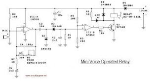
This circuit diagram represents a voice-operated relay. It functions similarly to a sound-activated switch circuit, which activates or deactivates the switch based on sound input. The output switch of this circuit operates through a relay. The voice-operated relay circuit typically...

The SA607 is a low voltage, high-performance monolithic FM intermediate frequency (IF) system that includes a mixer, oscillator, two limiting intermediate frequency amplifiers, a quadrature detector, a logarithmic received signal strength indicator (RSSI), a voltage regulator, and audio and...
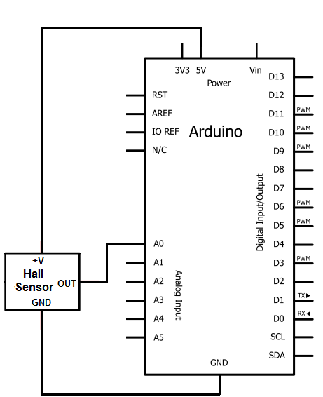
The Hall effect sensor utilized in this circuit is the A1302 Hall effect sensor manufactured by Allegro. This integrated circuit (IC) is capable of detecting magnetic fields. It will be connected to an Arduino, allowing the Arduino to read...
In spite of the improvement of communication link and despite all progress in advanced communication technologies, there are still very few functioning commercial wireless monitoring systems, which are most off-line, and there are still a number of issues to...
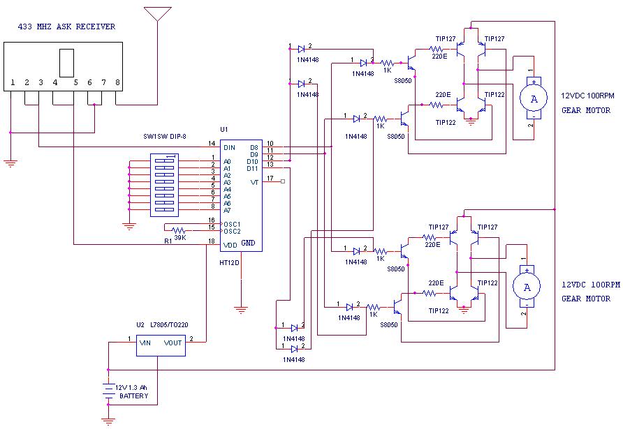
A remote-operated spy robot circuit can be controlled using a wireless remote controller. It captures audio and video information from the surroundings and transmits this data to a remote station via RF signals, with a maximum range of 125...
836MHz RF2347 low noise amplifier circuit diagram. The RF2347 is a low noise amplifier (LNA) designed for operation at a frequency of 836 MHz. It is typically used in RF applications where signal amplification is critical, such as in communication...