
Handy Time Delay With Relay Output

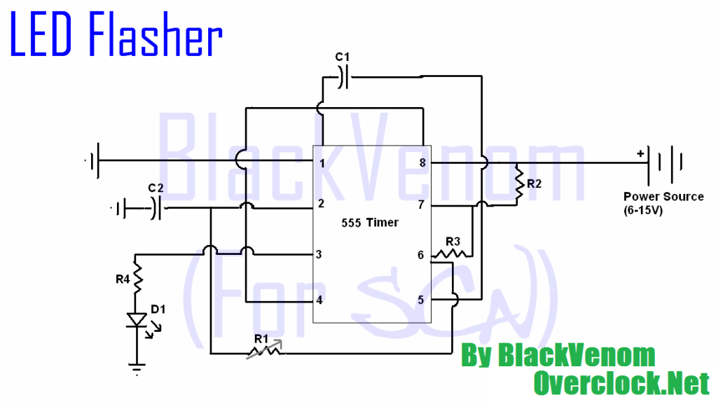
The circuit operates by utilizing a timing element, typically a resistor-capacitor (RC) network, which sets the delay period before the relay is activated. Upon powering the circuit, the capacitor begins to charge through the resistor, and the voltage across the capacitor increases gradually. Once this voltage reaches a predetermined threshold, it triggers a transistor or a similar switching device that energizes the relay coil, closing the relay contacts and allowing current to flow to the load.
The time constant (τ) of the RC network is calculated using the formula τ = R × C, where R is the resistance in ohms and C is the capacitance in farads. The delay time can be adjusted by selecting appropriate values for the resistor and capacitor. For instance, a larger resistor or capacitor will result in a longer delay, while a smaller resistor or capacitor will shorten the delay.
In addition to the RC timing circuit, it is essential to include protective components such as diodes across the relay coil to prevent back EMF from damaging the transistor when the relay is de-energized. A zener diode may also be incorporated to safeguard against voltage spikes that could occur during the switching process.
This circuit can be employed in various applications, including automotive lighting, industrial automation, and home appliances, where delayed activation is required to ensure proper system operation. Proper layout and component selection are crucial for achieving the desired performance and reliability of the circuit.This circuit is designed to provide delayed relay switching action at power on. The delay is a function of the time constant produced by the combination o.. 🔗 External reference
Related Circuits
This device is designed for individuals seeking to achieve a tan while minimizing excessive exposure to sunlight. It utilizes electrolytic capacitors as one of its components. The tanning device operates by utilizing a controlled exposure mechanism that regulates the intensity...
All of the components in this list are generally available through RadioShack for less than $20. It is highly recommended to use a breadboard for assembly, as mistakes are common for first-time builders, and soldering can complicate troubleshooting. This...
In this circuit, an LM339 quad voltage comparator is utilized to generate a time delay and control a high current output at low voltage. Approximately 5 amps of current can be sourced using a pair of fresh alkaline D...
A switched timer for intervals of 5 to 30 minutes incremented in 5 minute steps. Simple to build, simple to make, nothing too complicated here. However, you must use the CMOS type 555 timer designated the 7555; a normal...
This delay can be used in power amplifiers to prevent the fuses from failing when the amplifier is turned on. The circuit is very simple with a relay that is turned on when C2 and C3 are charged. If...
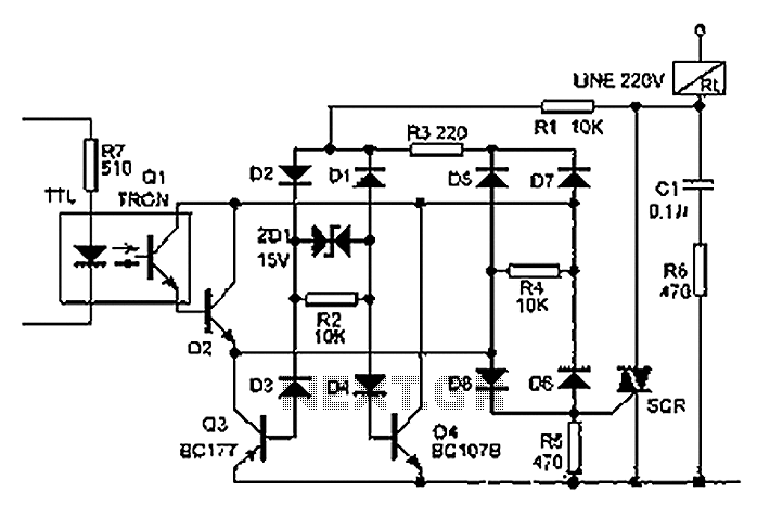
The relay illustrated in the figure operates based on non-inductive analog circuit theory. Its working principle involves a 220V power supply connected to a load (RL), resistors (R1, R3, R6), diodes (D1 to D8), and a zener diode (ZD1)....