
5 to 30 Minute Timer

Timing = 1.1 C1 x R1
Note that R1 has a value of 8.2M with S3 at position "a" and 49.2M at position "f".
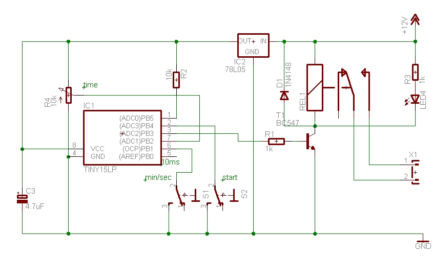
The circuit described is a switched timer utilizing the CMOS 7555 timer IC, which is specifically chosen for its low power consumption and enhanced performance characteristics compared to the standard 555 timer. This timer is designed to provide adjustable timing intervals ranging from 5 to 30 minutes, with the increments set at 5-minute steps.
The primary components of this circuit include the 7555 timer IC, a low-leakage capacitor (C1), and a variable resistor network controlled by Switch 3 (S3). The timing interval is determined by the equation:
Timing = 1.1 * C1 * R1
In this equation, C1 represents the capacitance in farads, and R1 represents the resistance in ohms. The choice of a Tantalum Bead capacitor is critical due to its low leakage properties, which ensures that the timing accuracy is maintained over extended periods.
The resistance value of R1 is adjustable via S3, which can be set to different positions to provide various resistance values. At position "a", R1 is set to 8.2MΩ, while at position "f", it is adjusted to 49.2MΩ. This range allows for fine-tuning of the timing interval to achieve the desired timing output.
The circuit operates by charging the capacitor C1 through the resistor R1. The time it takes for the capacitor to charge to a specific threshold voltage determines the timing interval. When the timer is activated, the output will remain high for the duration calculated by the aforementioned equation before reverting to a low state, effectively creating a timed output pulse.
The simplicity of the circuit design makes it accessible for various applications, including timing relays, delay circuits, or any scenario where a precise timing interval is required. Proper attention must be paid to the selection of components, particularly the use of the CMOS 7555 timer and the low-leakage capacitor, to ensure reliable operation and accurate timing performance.A switched timer for intervals of 5 to 30 minutes incremented in 5 minute steps. Simple to build, simple to make, nothing too complicated here. However you must use the CMOS type 555 timer designated the 7555, a normal 555 timer will not work here due to the resistor values. Also a low leakage type capacitor must be used for C1, and I would strongly suggest a Tantalum Bead type.
Switch 3 adds an extra resistor in series to the timing chain with each rotation, the timing period us defined as :- Timing = 1.1 C1 x R1 Note that R1 has a value of 8.2M with S3 at position "a" and 49.2M at position "f". This 🔗 External reference
Related Circuits
The time can be set using a potentiometer ranging from 1 minute to 1023 minutes, approximately 17 hours. A pushbutton initiates the timing process, activates a relay, and the timer will deactivate the relay once the set time has...
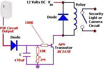
The following circuit illustrates a PIR Sensor Timer Circuit Diagram. Features include a simple design, enhanced accuracy, and efficiency. Components involved are a diode, among others. The PIR (Passive Infrared) Sensor Timer Circuit is designed to detect motion through infrared...
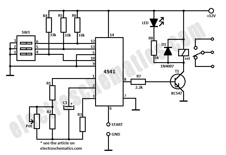
To initiate the timing process, there are two options available: either connect the START point to ground (GND), in which case the timer activates when connected to the voltage supply, or employ a switch to start the timer. The timing...
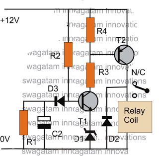
The post discusses a simple delay ON circuit that enables a connected load at the output to be activated with a predetermined delay after the power switch is turned ON. This circuit can be utilized in various applications that...
The purpose of this circuit is to power a lamp or other appliance for a given time (30 minutes in this case), and then to turn it off. It is useful when reading at bed by night, turning off...
This circuit is simple to build and straightforward, but it requires the use of the CMOS type 555 timer designated as the 7555, as a standard 555 timer will not function properly due to the resistor values. A low...