
Hartley oscillator

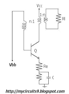
The Hartley Oscillator is a type of electronic oscillator that utilizes an inductor-capacitor (LC) circuit to generate oscillations. It is characterized by its use of two inductors and one capacitor, which form a resonant circuit. The feedback mechanism is achieved through a tapped coil, allowing for variable frequency operation.
In a typical Hartley oscillator circuit, the two inductors are often connected in series, and one of them is tapped to provide feedback to the amplifier stage. This feedback is crucial for maintaining oscillations, as it ensures that the output signal is amplified and fed back into the circuit in phase with the input signal. The frequency of oscillation is primarily determined by the values of the inductors and the capacitor, following the formula:
\[ f = \frac{1}{2\pi\sqrt{L_{total}C}} \]
where \( L_{total} \) is the equivalent inductance of the two inductors. The configuration allows for easy tuning of the oscillation frequency by adjusting the tap point or changing the values of the inductors or the capacitor.
The Hartley oscillator is commonly used in radio frequency applications, signal generators, and other electronic devices where stable oscillations are required. Its ability to produce a sine wave output makes it suitable for various applications, including modulation and demodulation in communication systems. The design can be implemented using discrete components or integrated circuits, depending on the required specifications and performance criteria.
Overall, the Hartley oscillator is valued for its simplicity, reliability, and ease of frequency adjustment, making it a popular choice in oscillator design.The Hartley Oscillator is an L C oscillator that derives its feedback from magnetically coupled energy in a tapped coil. Hartley oscillator are inductively coupled variable frequency oscillators. 🔗 External reference
Related Circuits
The schematic diagram depicted in Figure 1 is designed to synthesize a sinusoidal waveform with a frequency range of 0.01 Hz to 1 MHz. A clock signal is supplied to the input of the binary counter IC1, with a...
In the Hartley circuit, the amplified energy from the plate circuit is fed back to the grid circuit through fluctuating magnetic fields. Both circuits utilize magnetic feedback. The Hartley circuit employs a single coil, with part of it situated...
The Wien-bridge oscillator consists of an operational amplifier (OA) in a non-inverting configuration with a gain of 1 + R2/R1 and an RC feedback network. The Wien-bridge oscillator is a type of electronic oscillator that generates sine waves. It employs...
Initially, there is a voltage Vc on capacitor C1 that is greater than Vbb - Vg, where Vg is the cutoff base-emitter voltage and g represents Gamma. Consequently, the transistor is in the off state, and capacitor C1 discharges...
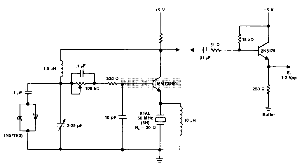
The diagram illustrates a 50 MHz oscillator functioning at its third harmonic. The collector load resistor R1 has been increased due to the rise in the quartz crystal's internal series resistance Rs, which escalates with frequency in the VHF...
A crystal oscillator, particularly a low-frequency variant, can be effectively constructed using an operational amplifier (op-amp) as the amplification component. Below is the schematic diagram of this circuit. The crystal oscillator circuit utilizes the properties of a quartz crystal to...