
hartley oscillators

The Hartley oscillator is a versatile circuit that operates based on the principle of feedback and resonance. The core components include a center-tapped inductor (L1), which is crucial for establishing the oscillation frequency, and variable capacitors (C1 to C3, along with Cv and Ct) that allow for tuning across a specified frequency range. The feedback mechanism is formed by connecting the source of the JFET to a specific point on the inductor, which is essential for maintaining the oscillation.
Capacitor C4 plays a significant role in isolating the oscillator from loading effects caused by subsequent stages. It is typically selected to be as small as possible while still providing adequate drive to the buffer amplifier. The choice of using a trimmer capacitor for C4 is common among hobbyists, as it allows for fine-tuning of the circuit.
The resistors, silicon diode, and zener diode are standard components that serve specific functions within the circuit. The zener diode is particularly important for providing a stable voltage supply, which is critical for the reliable operation of the oscillator. The silicon diode may be included for signal rectification or protection purposes.
For inductance, the design specifies that L1 should exhibit approximately 180 ohms of reactance at the desired frequency of 5 MHz. This can be achieved with a calculated inductance of around 5.7 µH. The construction of the inductor, whether air-cored or toroidal, must adhere to specific winding techniques to ensure optimal performance. The choice of wire gauge and number of turns directly influences the inductance value, and the feedback tap point must be carefully positioned to achieve the desired oscillation characteristics.
The tuning mechanism is facilitated by variable capacitors, allowing the oscillator to operate within the specified frequency range. The air variable capacitor's range of 10.5 pF to 105 pF provides sufficient flexibility to accommodate slight variations in the circuit components and ensures that the tuning ratio remains within the desired limits.
Overall, the Hartley oscillator circuit is a fundamental design in electronics that exemplifies the principles of feedback, resonance, and tuning. The careful selection of components and their arrangement within the circuit is essential for achieving stable oscillation and desired output characteristics.Hartley oscillator are inductively coupled, variable frequency oscillators where the oscillator may be series or shunt fed. Hartley oscillators have the advantage of having one centre tapped inductor and one tuning capacitor.
This arrangement simplifies the construction of a Hartley oscillator circuit. Here I`ll present the schematic for my old favourite, together with a buffer stage and an amplifier stage which should deliver about 5V P/P into a 50 ohm load. We`ll discuss each relevant stage and produce some rule-of-thumb design info. Because the consensus comes down in favour of FETS and I`m big enough to lay aside my prejudices in the noble cause of advanced education we`ll use a FET oscillator. Nothing to do with a few friends who might belt me up! Now I chose a 2N4416A FET purely because I bought a big bag of them years ago and have them on hand. You could use any general purpose JFET you can readily obtain. Note the 2N4416A is a metal can and the case is grounded. Note: I have been asked a number of times the function of C4 in this circuit. Capacitor C4 is to reduce the loading on the tuned circuit components. It may be as small as possible consistent with being able to provide sufficient drive to the succeeding buffer amplifier stage.
Often the home constructor will often make C4 a trimmer. The other components are bog standard. The two resistors, silicon diode and zener diode need never change, capacitor C5 is about right for this frequency. C6 can be selected to give higher / lower output to the buffer amplifier. Smaller C6 values give lower output and conversely higher values give larger output. The silicon diode I`ll explain later, the zener diode is to give a regulated 6. 2 volt supply. Now there is NOTHING sacred about my frequency determining capacitor combination O. K. Too many people look at these kind of circuits and think they must duplicate everything literally, not so.
This is just a typical representation. C1 to C3 plus Cv and Ct are just a combination of parallel and some series capacitors all designed to give us a bit of flexibility with the tuning range. Cv could easily be replaced by two back to back tuning diodes. What you need to do to get the circuit to work is to have an inductive reactance for L1 of around about 180 ohms.
At 5 Mhz this works out at about 5. 7 uH and, if you don`t know how I arrived at that figure I seriously recommend you spend some time on my other tutorials such as Basics and LC Filters. The important aspect is that the feedback point from the source of the JFET connects to about 25% of the windings of L1 from the ground end.
Now I`ve depicted an air cored inductor. It could be, just as one example among a great many, 18 - 19 turns of #20 gauge wire on a 25. 4 mm (1") diameter form spread evenly over a length of about 25. 4 mm (1"). The tap would be at about 4 1/2 turns. Check that out with the formula`s I taught you elsewhere. Alternatively, with degraded performance, you could use a T50-6 toroid and wind say 37 turns of #24 wire (5. 48 uH) tapping at 9 turns. The AL factor for a T50-6 is 40. Again do the other tutorials if necessary, I`m not going to repeat old work and it`s going to be even harder from here on.
I`ll thoroughly explain new concepts, not the old. So if we are to have our oscillator working at about 5 Mhz, we know the LC is 1013 and if L is say 5. 7 uH then total C for resonance (just like LC Filters eh!) is about 177 pF. We want to be able to tune from 5000 to 5100 Khz a tuning ratio of 1. 02 which means a capacitance ratio of 1. 04 (min to max). Let`s fiddle with some numbers! I have a Jackson Bros. air variable capacitor (very Rolls-Royce) which swings from 10. 5 pF to 105 pF, a typical 10:1 ratio in air variables. This I will use for Cv. If the total swing is 1. 04 (actually 1. 0404:1) and Cmax is 177 pF it follows Cmin is 170 pF. A variation of only 7 pF (roughly). Now we`re treading on unsafe 🔗 External reference
Related Circuits
The multiplication operation required to generate a signal with a frequency equal to the difference of the input frequencies can be implemented in various ways. A multiplied signal typically appears when two signals are added and subsequently processed through...
A basic Wien Bridge Oscillator utilizes a filament lamp in conjunction with an operational amplifier (op-amp). The property of filament lamps, specifically the non-linear increase in resistance of the tungsten filament as it heats, plays a crucial role in...
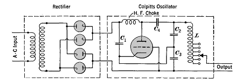
High frequencies are defined as those above 50,000 cycles per second. For industrial power supplies, the Golpitts circuit or the coupled-grid self-excited oscillator circuit is most commonly used. In either circuit, the alternating supply voltage is stepped up through...
In applications where good frequency stability is essential, such as radio transmitters, basic LC oscillators may not maintain their frequency without drifting. This drift can be caused by small changes in supply voltage, although stabilized power supplies can help...
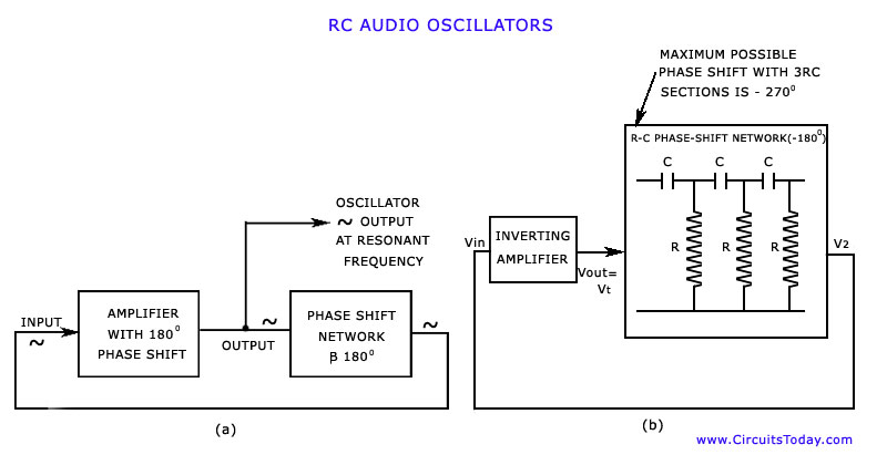
The discussion has focused on oscillators that utilize L-C tuned circuits, which create a 180° phase shift due to inductive or capacitive coupling, in addition to another 180° phase shift produced by the transistor itself. These L-C oscillators are...
Millimeter-wave frequency bands are appealing due to their wide available bandwidths. Signals can be generated in various ways; however, for each type of oscillator, electronic tuning of the source in a defined and controlled manner is desirable. Employing a...