
Mixers and oscillators
The described circuit utilizes a combination of analog switches and operational amplifiers to achieve frequency multiplication through non-linear mixing. The architecture allows for flexible signal manipulation, where the switching action of the 4053 analog switch enables the selection between the original and inverted signals, effectively creating the necessary frequency components. The use of opamps configured as inverting amplifiers ensures that the signal is adequately boosted before processing, which is crucial for maintaining signal integrity in subsequent stages.
The integration of a Schmitt trigger and an integrator opamp provides a means to shape the output waveform from a square wave to a triangle wave, enhancing the waveform's quality for applications requiring sine-like outputs. The circuit's design is particularly advantageous for low-power applications, given the efficiency of the TL072 dual-opamp IC and the VCO in the 4046 PLL. This configuration is suitable for use in various electronic applications, including signal processing, modulation, and synthesis, where precise frequency control and waveform shaping are essential.
Overall, the circuit exemplifies an effective approach to generating and manipulating frequencies in a controlled manner, addressing common challenges associated with non-linear mixing and waveform generation.The multiplication operation that is required to generate a signal of a frequency equal to the difference of the input frequencies, can be implemented in several ways. Actually a multiplied signal generally also appears when two signals are added and subsequently put through a non-linear device, like a pn-junction in a diode or transistor.
Example s of this type of mixer are a transistor biased into non-linear operation, a simple two-diode mixer and more advanced four-diode balanced mixers. When using a square wave oscillator, the multiplication operation simply comes down to reversing the polarity of the bat signal at the frequency of the local oscillator.
This can be implemented by using an analog switch to switch between the bat signal and an inverted version of the bat signal. In the picture on the right a basic implementation of this idea is shown. The leftmost opamp is configured as an inverting amplifier to give the signal some extra boost. The rightmost opamp is an inverting amplifier with gain -1. A 4053 is used to switch the output to either the output of opamp 1A or opamp 1B. The positive inputs of the opamps are biased at half the supply voltage. These can be built with a single opamp or a NE555 (pdf) for example. In these type of oscillators, the frequency is inversely proportional to the RC product. The nonlinear (inversely proportional) relationship between the RC product and the frequency is not very convenient.
This can be alleviated somewhat by using a logarithmic potmeter, but in that case the clockwise position of the potmeter corrresponds to the lowest frequency. These use a resonant LC-circuit to generate a relatively pure frequency (little harmonics). Disadvantages are the nonlinear relationship between LC and frequency and the lack of variable L or C with sufficient range (either L or C needs to be tuned in a 1:100 range to get frequencies between 10 kHz and 100 kHz).
Using an LC-oscillator at high frequencies with the double heterodyne method solves both problems to some extent. These are generally special ICs where the output frequency depends on the input voltage. The VCO inside a 4046 PLL (pdf) is very convenient to use for example; it has a sufficient linear relationship between voltage and frequency and uses very little current, however it generates a square wave instead of the more desirable sine wave and it is sensitive to supply voltage.
A very nice circuit is shown on the right (source: National Semiconductor, Application Note 31, February 1978, Opamp circuit collection). It outputs a triangle wave with a frequency essentially independent of supply voltage. The triangle wave is already quite close to the ideal sine wave, with the 3rd harmonic down by 19 dB.
The opamp on the left is configured as a schmitt-trigger, whose treshold determines the triangle`s amplitude. The opamp on the right is configured as an integrator, converting the square wave from the other opamp into a triangle.
To use this circuit with a single supply voltage, the grounded inputs on the opamps should be connected to half the supply voltage (by means of a resistive divider). For the opamps, a single TL072 dual-opamp IC can be used. 🔗 External reference
Related Circuits
A basic Wien Bridge Oscillator utilizes a filament lamp in conjunction with an operational amplifier (op-amp). The property of filament lamps, specifically the non-linear increase in resistance of the tungsten filament as it heats, plays a crucial role in...
The mixer circuit described features three line inputs and three microphone inputs. The microphone inputs are designed for low impedance dynamic microphones with a range of 200 to 1000 ohms. Alternatively, an electret condenser microphone (ECM) can be used,...
The variations, which effectively form an alternating signal, will be transmitted through the coupling capacitor to the subsequent stage, indicated by the arrow to the right. One variable resistor can be substituted with another. R1 can be replaced with...
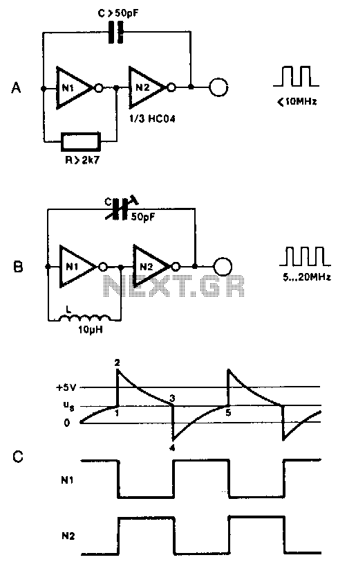
Two inverters, one resistor, and one capacitor are sufficient to create an HC(T)-based oscillator that operates reliably up to approximately 10 MHz. The use of two HC inverters results in a fairly symmetrical rectangular output signal. In this configuration,...
Online Electronics Course covering the Science of Radio Frequency Engineering, including topics such as Electronics, Microwave Technology, Waveguides, Antennas, Tubes, Historical Context, Klystrons, Magnetrons, Traveling Wave Tubes (TWT), Internet of Things (IoT), Klystrodes, Broadcast Equipment, and Repair Techniques. The online...
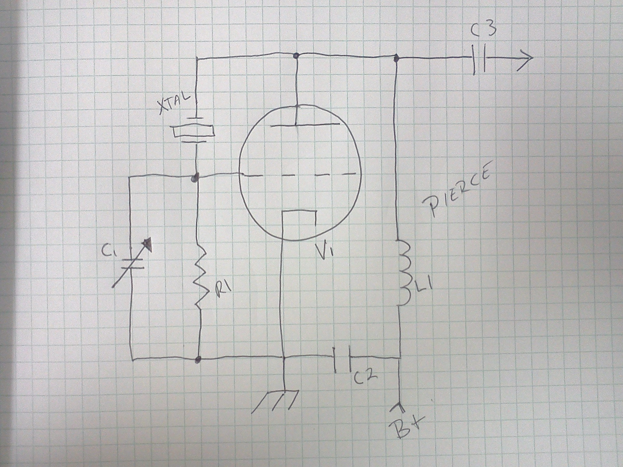
Colpitts oscillators are similar to the shunt-fed Hartley circuit; however, the Colpitts oscillator uses two series capacitors in its LC circuit instead of a tapped inductor. The connection between these two capacitors serves as the center tap for the...