
Headlight Alarm Circuit

This circuit utilizes two transistors, Q1 and Q2, to control the operation of a piezoelectric buzzer and an LED in relation to the vehicle's ignition and headlight systems. The base of transistor Q1 is directly interfaced with the ignition circuit, typically at the ignition switch fuse, which serves as a convenient connection point. The piezoelectric buzzer is connected to the instrument-panel light fuse, ensuring that its operation is linked to the status of the vehicle's lighting system.
Under normal conditions, with the headlights turned off, the circuit remains inactive as no current flows to the buzzer. However, when the headlights or parking lights are activated, the instrument panel lights up, providing the necessary voltage to the buzzer. The operational state of the circuit is critically dependent on the ignition switch's position.
When the ignition switch is in the 'ON' position, both transistors Q1 and Q2 are biased, effectively isolating the buzzer and LED from the circuit and preventing them from activating. Conversely, if the ignition switch is turned off while the headlight switch remains engaged, transistor Q1 turns off, but transistor Q2 remains biased. This condition allows current to flow through the circuit, generating sufficient voltage across the piezoelectric buzzer and the LED, resulting in the buzzer sounding and the LED illuminating.
This configuration not only provides a visual and audible alert when the headlights are left on with the ignition off, but it also ensures that the circuit can be easily monitored and serviced through its connections to the vehicle's existing electrical systems. The use of transistors for control enhances reliability and reduces the risk of accidental activation when the vehicle is not in use. The base of Ql is connected to the car`s ignition circuit; the easiest point to make that connection is at the ignition switch fuse in the car`s fuse panel. Also, one side of the piezoelectric buzzer is connected to the instrument-panel light fuse; when the headlights or parking lights are on, the instrument panel is lit, too.
When the headlights are off, no current reaches the buzzer. Therefore, nothing happens. What happens when the headlights arc on depends on the state of the ignition switch. When the ignition switch is on, transistors Ql and Q2 are biased on, effectively removing the buzzer and the LED from the circuit. When the ignition switch is turned off, but the headlight switch remains on, transistor Ql is turned off, but transistor Q2 continues to be biased on. The result is that the voltage across the piezoelectric buzzer and the LED is sufficient to cause the buzzer to sound loudly and the LED to light.
Related Circuits

During the charging process, the green light-emitting diode (LED) VLi indicates that the battery is sufficiently charged, while the red light-emitting diode (LED) VLz illuminates when the battery is low. The circuit involves two light-emitting diodes (LEDs) serving as indicators...
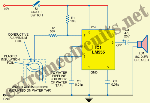
The State Jal Boards provide water for a limited duration each day. The timing of water supply is determined by the management, and the public is not informed of this schedule. The operation of State Jal Boards typically involves a...
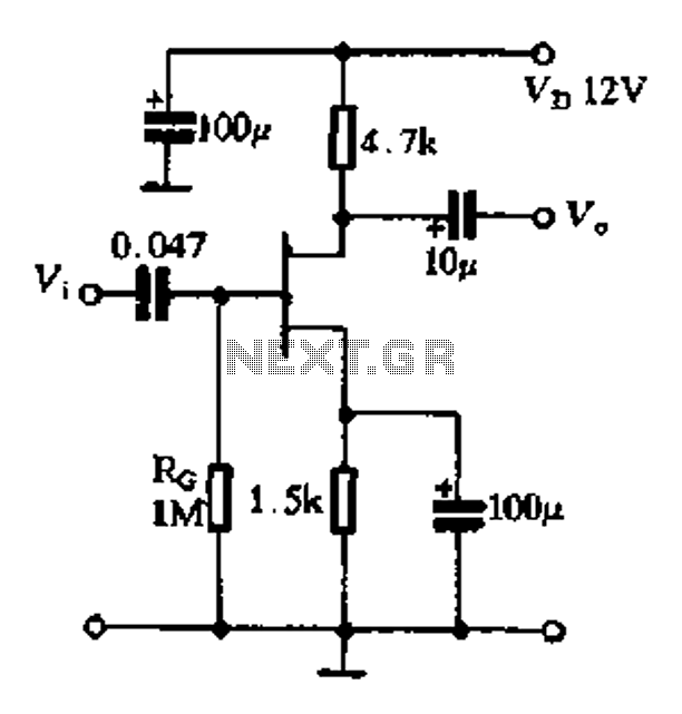
The FET exhibits a high input impedance, a low noise figure, anti-crosstalk capabilities, and good mutual interference performance, making it increasingly utilized in electronic circuits. FET amplifiers can be configured in various ways, including as common source (equivalent to...
This circuit features a white LED-based emergency light that provides several benefits. It is exceptionally bright due to the incorporation of white LEDs. The light activates automatically when the mains supply is interrupted and deactivates when mains power is...
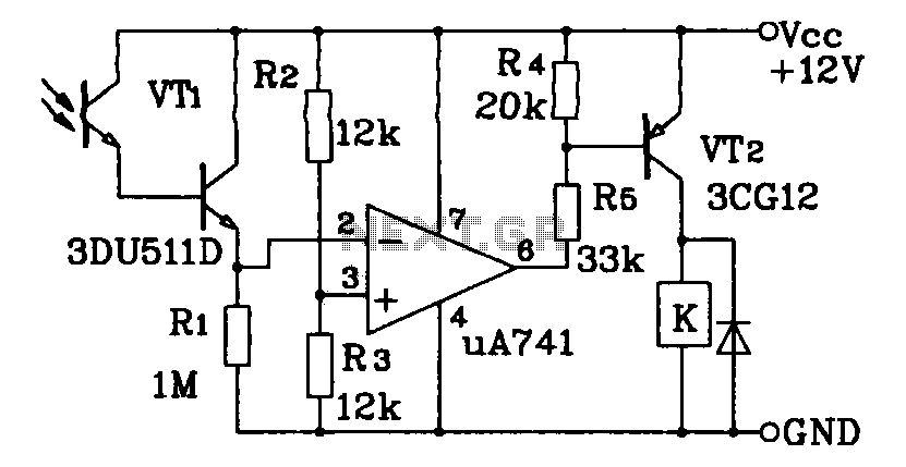
This circuit application utilizes a Darlington phototransistor for light-triggered switching. The design incorporates a Darlington phototransistor and an operational amplifier (op-amp), allowing the circuit to respond to very faint light levels. The circuit can be modified to trigger in...
This schematic represents a version of a simple LED chaser. A 555 timer is not utilized due to its high cost at local electronics stores, which is over $4 CAD. Instead, an oscillator is constructed using two sections of...