
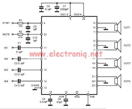
Headphone amplifier with TDA2004

The bandwidth restriction for each unit is regulated by the combination of specific components. For instance, the combination of resistor R12 and capacitor C2, as well as resistor R13 and capacitor C15, is responsible for limiting the frequency response to 22KHz. This frequency cap ensures that the amplifier remains stable and does not oscillate at high frequencies, which could potentially damage the connected headphones.
Furthermore, resistors R5 and R10 play a crucial role in impedance matching. These resistors help adapt the impedance of the earphones, ensuring optimal power transfer from the amplifier to the earphones. Impedance matching is particularly important in this context as it prevents signal loss and distortion, thereby improving the overall sound quality.
In summary, this medium-power operational amplifier has been designed with a focus on headphone amplification, featuring a dual-amplifier setup, a voltage gain of 40dB per channel, a bandwidth limit of 22KHz, and dedicated components for impedance matching.A opamp. medium power, here its used as amplifier of headphones with possibility drive low loads. It contains in a nutshell two amplifiers. The voltage gain, has been determined in 40dB, from the R3-4 and R11-12, for each channel, respectively. The restriction of bandwidth for each unit is regulated by the combination of R12, C2 and R13, C15, in 22KHZ.
The R5, R10 attend to the adaptation of impedance earphones. 🔗 External reference
Related Circuits
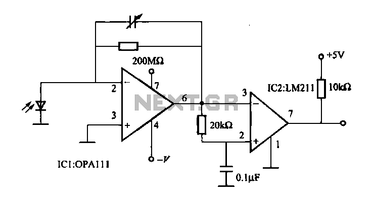
The OPA111 optical receiver amplifier features a feedback resistor of 200 MΩ, which is crucial due to the high gain of the amplifier. The OPA111 is designed to receive signals transmitted over optical fiber, specifically at a rate of...
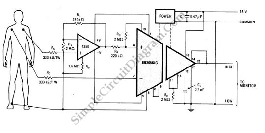
The circuit illustrated in the schematic diagram below is designed to monitor the heart pulses of a patient. This circuit buffers and amplifies the heart pulses. The heart pulse monitoring circuit typically consists of several key components that work together...
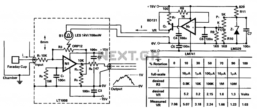
To amplify small current signals, such as those from an electron collector inside a vacuum chamber, it is beneficial for reasons related to noise and bandwidth to utilize a "head amplifier" connected to the chamber. The operational amplifier N1...
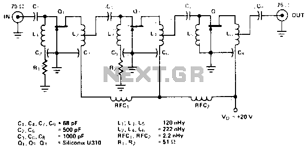
The amplifier circuit is designed for a center frequency of 225 MHz, with a bandwidth of 50 MHz at 1 dB, low input voltage standing wave ratio (VSWR) in a 75-ohm system, and a gain of 24 dB. Three...
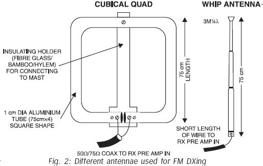
FM transmissions can be received within a range of 40 km. In fringe areas, the signal may be very weak. FM DXing refers to the practice of receiving distant stations (1500 km or more) on the FM band (88-108...
The input capacitor is used for low-frequency cut-off, with a standard value of 0.1 µF, resulting in a cut-off frequency of approximately 16 Hz. The input capacitor plays a crucial role in filtering unwanted low-frequency signals in electronic circuits. By...