
Headphone Class-A Power Amplifier

Power requirements are usually in the 10 to 100mW range, and this is quite sufficient to cause permanent hearing damage. With the current set for 330 mA as suggested, this amp will be able to drive a minimum of 2 (but probably 3) sets of headphones at once. With 40 Ohm 'phones, it can give a maximum power of over 150 mW, so caution is needed to prevent hearing (and headphone) damage. Even with 8 ohm 'phones, power will be about 110mW - more than enough to have you asking people to repeat everything they say!
Caution! Just in case you missed it, headphones are easily capable of causing permanent irreparable hearing damage. Modern dynamic headphones are very efficient (typically well over 90dB SPL per milliwatt) and will reach full volume with just a few milliwatts of input. A mere 100 mW will therefore provide a peak SPL of around 110dB SPL. The recommended maximum exposure to this sound level is less than 5 minutes in any 24 hour period! The final circuit for the DoZ headphone amp is shown in Figure 1. It is almost identical to the original (well, apart from the output transistors and size of C3, it is identical), and there is no longer the need for massive heatsinks and TO-3 output transistors. As shown, there are outputs for 2 sets of headphones. Needless to say, only one channel is shown - the other is identical. Although MJL4281 transistors are shown in the circuit diagram, you can use cheaper devices for a headphone amp. If you want the highest possible reliability and best performance, those shown are a very good choice. Alternatives are TIP35 (A, B or C), MJL21194, or TIP/MJE3055. TO3 devices can also be used, but must be mounted off the PCB. As I have said before, this amp needs a fairly good heatsink, as do all Class-A amplifiers. Even 'though this amp runs at very low current, a good heatsink is recommended. Thermal resistance should ideally be no greater than about 2°C/W, so with a dissipation of about 10W the heatsink will be 20 degrees above ambient temperature. C3 should be 470uF to 1,000uF. The higher value is recommended if you intend to drive multiple sets of headphones. The value of C3 is determined based on the use of 120 ohm feed resistors to the headphones. You will need to use a higher value if you use a lower resistance (not recommended, but some 'phones seem to prefer lower source impedance). For final testing you will need a multimeter. As shown in the power supply circuit below, use a 10 Ohm resistor in series with the power supply positive lead. When you measure 1 volt across this resistor, this means that the amplifier is drawing 100 mA. The resistor remains in circuit, providing a useful reduction in supply ripple. You will lose about 3.3 V at operating current, and a 5W resistor is sufficient - it will get slightly warm. The output resistors (120 Ohm) should be rated for at least 2 Watts - a pair of 220 ohm 1W resistors in parallel will do just fine (the absolute value is not critical). Based on a maximum voltage of 10V RMS and a feed resistance of 120 ohms, the following table shows what peak power you should expect into various impedance headphones. Reducing the feed resistance will increase the power applied, probably to the detriment of your ears and the headphones themselves.
The Class-A headphone amplifier circuit is designed to provide high-fidelity audio output while minimizing distortion and noise, crucial for personal listening applications. The circuit typically employs a pair of output transistors, such as MJL4281, which are selected for their linear performance in Class-A operation. The configuration allows for a low output impedance, ensuring that the amplifier can drive headphones effectively without significant damping factor issues.
The power supply for the amplifier should be capable of providing a stable voltage, ideally around 10V RMS, and must be designed to handle the necessary current draw, specified at 330 mA for optimal performance. The 120-ohm feed resistors serve to match the output impedance to the expected headphone load, adhering to the IEC 61938 standard, which helps maintain audio fidelity across different headphone models.
Thermal management is a critical aspect of the design, as Class-A amplifiers are known for their heat generation due to continuous current flow. A heatsink with a thermal resistance of ideally no more than 2°C/W should be utilized to dissipate the heat effectively, preventing thermal overload and ensuring long-term reliability.
Capacitance at C3 plays a vital role in the amplifier's ability to manage power supply fluctuations, especially when driving multiple headphone sets. The recommended capacitance range of 470uF to 1,000uF allows for sufficient energy storage, accommodating transient demands without compromising audio quality.
In testing, the use of a 10-ohm series resistor provides a convenient method for monitoring current draw, ensuring that the amplifier operates within safe limits. The output resistors must be rated appropriately to handle the power levels, with a minimum of 2 watts recommended for reliable operation.
The circuit design emphasizes user safety, particularly regarding the potential for hearing damage, by limiting output power and providing guidelines for maximum exposure to high sound levels. This attention to detail in the design and implementation of the Class-A headphone amplifier ensures that users can enjoy high-quality audio without compromising their hearing health.Class-A is ideal for this application, since headphones are such an intimate way of listening. An amplifier for 'phones should be as clean and free from crossover distortion as possible, and must also be quiet. A background of hiss and hum does nothing to enhance the listening experience. Headphone amps are somewhat misunderstood, but in reality there are few points that need to be made. Most 'phones are designed to be operated with a source resistance of 120 ohms, and damping factor (as applied to conventional loudspeakers) is largely irrelevant.
The actual source impedance should have very little (if any) effect on the frequency response or dynamic behaviour, since there is no cavernous enclosure and no heavy cones to try to control. The IEC 61938 international standard recommends that headphones should expect a 120 ohm source (5V RMS maximum) - regardless of the headphone's own impedance. If the manufacturer followed this standard, the 120 ohm resistor used in this circuit will not affect sound.
Power requirements are usually in the 10 to 100mW range, and this is quite sufficient to cause permanent hearing damage. With the current set for 330 mA as suggested, this amp will be able to drive a minimum of 2 (but probably 3) sets of headphones at once.
With 40 Ohm 'phones, it can give a maximum power of over 150 mW, so caution is needed to prevent hearing (and headphone) damage. Even with 8 ohm 'phones, power will be about 110mW - more than enough to have you asking people to repeat everything they say!
Caution! Just in case you missed it, headphones are easily capable of causing permanent irreparable hearing damage. Modern dynamic headphones are very efficient (typically well over 90dB SPL per milliwatt) and will reach full volume with just a few milliwatts of input.
A mere 100 mW will therefore provide a peak SPL of around 110dB SPL. The recommended maximum exposure to this sound level is less than 5 minutes in any 24 hour period ! The final circuit for the DoZ headphone amp is shown in Figure 1. It is almost identical to the original (well, apart from the output transistors and size of C3, it is identical), and there is no longer the need for massive heatsinks and TO-3 output transistors. As shown, there are outputs for 2 sets of headphones. Needless to say, only one channel is shown - the other is identical. Although MJL4281 transistors are shown in the circuit diagram, you can use cheaper devices for a headphone amp.
If you want the highest possible reliability and best performance, those shown are a very good choice. Alternatives are TIP35 (A, B or C), MJL21194, or TIP/MJE3055. TO3 devices can also be used, but must be mounted off the PCB. As I have said before, this amp needs a fairly good heatsink, as do all Class-A amplifiers. Even 'though this amp runs at very low current, a good heatsink is recommended. Thermal resistance should ideally be no greater than about 2°C/W, so with a dissipation of about 10W the heatsink will be 20 degrees above ambient temperature.
C3 should be 470uF to 1,000uF. The higher value is recommended if you intend to drive multiple sets of headphones. The value of C3 is determined based on the use of 120 ohm feed resistors to the headphones. You will need to use a higher value if you use a lower resistance (not recommended, but some 'phones seem to prefer lower source impedance). For final testing you will need a multimeter. As shown in the power supply circuit below, use a 10 Ohm resistor in series with the power supply positive lead.
When you measure 1 volt across this resistor, this means that the amplifier is drawing 100 mA. The resistor remains in circuit, providing a useful reduction in supply ripple. You will lose about 3.3 V at operating current, and a 5W resistor is sufficient - it will get slightly warm. The output resistors (120 Ohm) should be rated for at least 2 Watts - a pair of 220 ohm 1W resistors in parallel will do just fine (the absolute value is not critical).
Based on a maximum voltage of 10V RMS and a feed resistance of 120 ohms, the following table shows what peak power you should expect into various impedance headphones. Reducing the feed resistance will increase the power applied, probably to the detriment of your ears and the headphones themselves.
🔗 External reference
Related Circuits
The problem with class-B amplifier design is that we start with an output stage in two halves, each with a non-linear response, which we then add together to try to give a linear response, i.e. so that a graph...
The circuit is fundamentally based on a well-tested simple microphone preamplifier design. A prototype of this circuit has been constructed and has demonstrated effective performance. The Sound Blaster soundcard series (SB16, SB32, AWE32, and AWE64) features a microphone input...
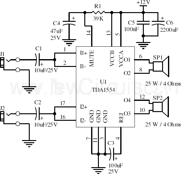
This document presents a 22-watt stereo audio power amplifier circuit diagram utilizing the TDA1554 integrated circuit from NXP Semiconductors (formerly known as PHILIPS Semiconductors). The circuit is designed to amplify stereo signals effectively. It dissipates approximately 28 watts of...
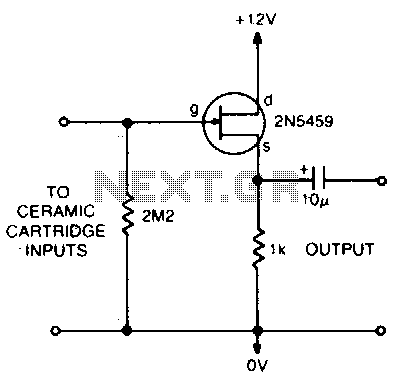
This circuit matches the very high impedance of ceramic cartridges, providing unity gain and low impedance output. By "loading" the cartridge with a 2.2MΩ input resistance, the cartridge characteristics are adjusted to closely compensate for the RIAA recording curve....
In certain electronic projects, there may be a need for an uncommon regulated voltage, particularly when the required voltage is very low. In such cases, conventional methods like using Zener diodes may not be feasible due to space constraints....
This amplifier circuit exhibits a very low power consumption, with a total current draw of 675 nA. The output voltage swing is 300 mV peak-to-peak (pp) with a gain of 20. The amplifier circuit is designed to operate with minimal...